
Tubular Ultrafiltration Membrane
PVDF & PES Tubular UF Membrane Modules for Industrial Wastewater Treatment
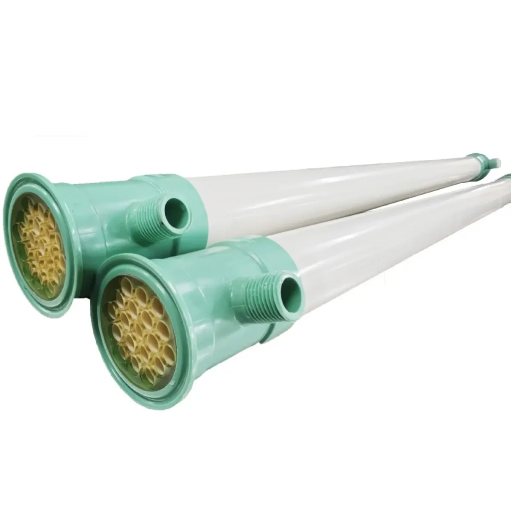
Tubular ultrafiltration membranes are used for solid-liquid separation in industrial processes involving high suspended solids, colloidal particles, emulsified contaminants and other challenging feed streams.
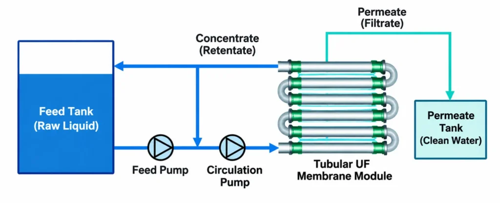
Unlike conventional hollow fiber UF modules, tubular membranes provide relatively large internal flow channels and can operate in crossflow filtration systems. The circulating liquid flows along the membrane surface while permeate passes through the membrane wall, helping reduce the accumulation of suspended solids.
Clear Environment provides tubular UF membrane modules for wastewater treatment projects, external membrane bioreactors and replacement applications.
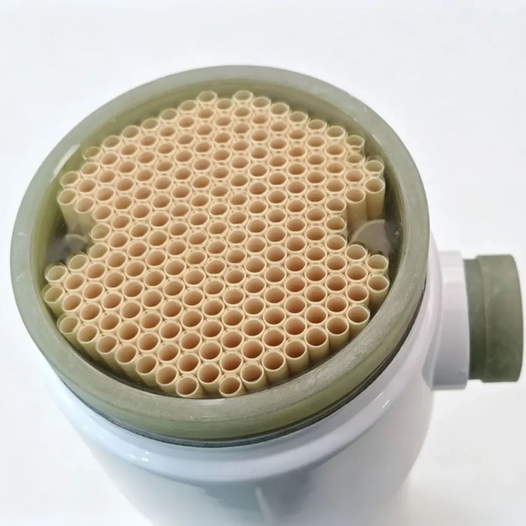
Available product configurations include 6 mm, 8 mm and 12 mm membrane channels, with different membrane materials, filtration ratings and module dimensions.
How Tubular Ultrafiltration Membranes Work
The tubular membranes use a supported polymeric membrane structure.
During crossflow filtration, feed liquid is pumped through the internal membrane channels. Part of the liquid passes through the membrane wall as permeate, while retained solids and other rejected components remain in the circulating stream.
The relatively large channel diameter helps accommodate feed liquids containing suspended solids that could rapidly block narrower membrane channels.
Three operating factors are particularly important:
Crossflow velocity: Sufficient circulation helps limit solids deposition on the membrane surface. However, increasing velocity also increases pumping energy consumption.
Transmembrane pressure (TMP): TMP provides the driving force for filtration. Higher pressure does not always produce a proportional increase in permeate flux, especially when membrane fouling or concentration polarization becomes significant.
Permeate flux: Actual operating flux depends on membrane characteristics, feed composition, temperature, solids concentration and cleaning conditions.
Tubular UF membrane systems therefore require a balance between filtration performance, circulation energy and long-term fouling control.
PVDF and PES Tubular Ultrafiltration Membranes
Membrane material and separation rating should be selected according to the actual filtration objective.
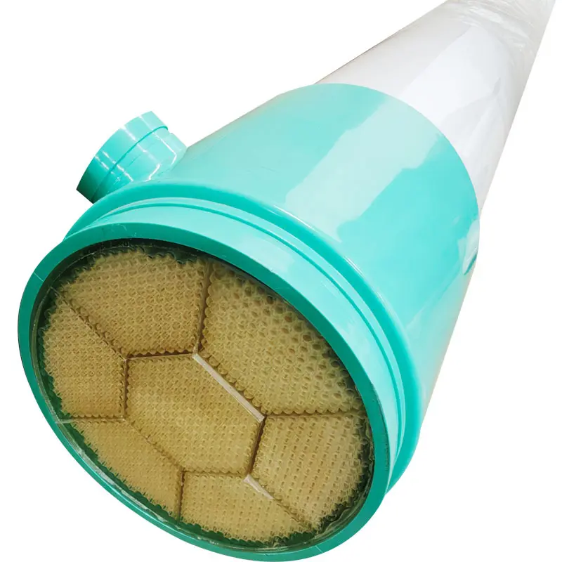
Our tubular membrane range includes PVDF and PES materials with different pore-size or molecular-weight-cut-off specifications.
PVDF Tubular Membranes
PVDF membrane options include a nominal 300,000 Da molecular weight cut-off. PVDF is used in a range of industrial membrane applications, with chemical compatibility and operating limits depending on the specific membrane construction.
PES Tubular Membranes
PES tubular membrane options are available with molecular weight cut-offs of 6,000, 10,000, 30,000 and 50,000 Da, depending on the selected membrane configuration.
These membranes may be considered where the separation objective requires retention of selected macromolecular components.
Important: Membrane MWCO is not an absolute particle-size cut-off and should not be used alone to predict the removal of dissolved organics, emulsified oil or other contaminants. Feed testing may be necessary to confirm separation performance.
Selection factor | Why it matters |
|---|---|
Membrane material | Chemical and cleaning compatibility |
MWCO / pore size | Separation characteristics |
Channel diameter | Hydraulic resistance and solids-handling capability |
Membrane area | Required number of modules |
Operating temperature | Material and module limitations |
Cleaning pH | Long-term membrane compatibility |
For other membrane configurations, explore our industrial ultrafiltration membrane options, including hollow fiber UF modules for different water treatment applications.
Tubular Ultrafiltration Membrane Models and Dimensions
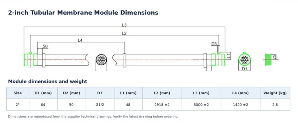
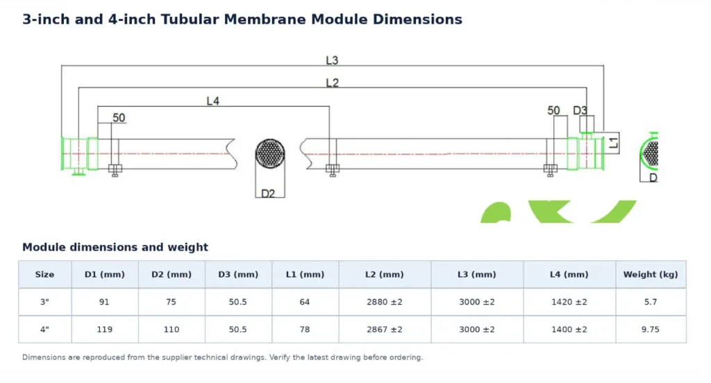
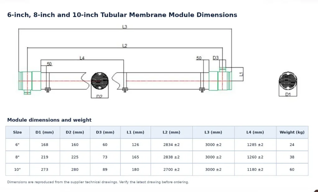
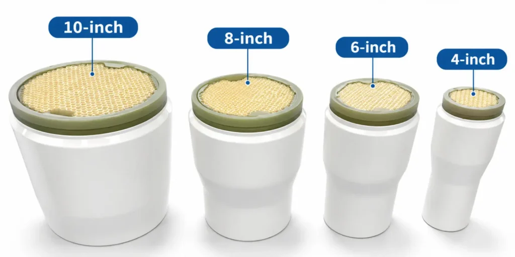
Tubular membrane modules are available in different channel diameters and housing sizes. The choice of module depends on the required membrane area, feed characteristics, circulation flow and installation space.
Understanding Tubular Membrane Model Numbers
For example, the T8-365-30 model designation indicates:
T8: Tubular membrane with an 8 mm internal channel diameter
365: Number of membrane channels
30: Nominal 3.0 m module length
Additional model suffixes may indicate membrane material, filtration rating or housing configuration.
For replacement orders, the complete model code should be checked against the latest drawing.
T8 Series – 8 mm Channel Tubular Membranes
| Module Model | Length (m) | Area (m²) | Channels | OD (mm) | Housing Material |
|---|---|---|---|---|---|
| T8-19-30 (2") | 3 | 1.4 | 19 | 50 | PVC |
| T8-37-30 (3") | 3 | 2.7 | 37 | 75 | PVC |
| T8-85-30 (4") | 3 | 6.4 | 85 | 110 | PVC |
| T8-201-30 (6") | 3 | 15.2 | 201 | 160 | PVC |
| T8-365-30 (8") | 3 | 27.2 | 365 | 225 | PVC |
| T8-577-30 (10") | 3 | 43 | 577 | 280 | PVC |
The T12 series features a 12 mm internal membrane channel diameter and is available in five standard module configurations, ranging from 0.8 m² to 16.8 m² of membrane area.
Compared with smaller-channel configurations, the larger flow passages may be advantageous for feed liquids containing suspended solids or materials with a higher risk of channel blockage. Final selection should consider membrane area, circulation requirements and wastewater characteristics.
T12 Series Technical Specifications
| Module Model | Channel ID | Channels | Membrane Area | Module Length | Module Diameter |
|---|---|---|---|---|---|
| T12-7-30 (2") | 12 mm | 7 | 0.8 m² | 3 m | 50 mm |
| T12-19-30 (3") | 12 mm | 19 | 2.1 m² | 3 m | 75 mm |
| T12-37-30 (4") | 12 mm | 37 | 4.2 m² | 3 m | 110 mm |
| T12-85-30 (6") | 12 mm | 85 | 9.6 m² | 3 m | 160 mm |
| T12-149-30 (8") | 12 mm | 149 | 16.8 m² | 3 m | 225 mm |
Operating Conditions for Tubular UF Systems
The operating conditions of a tubular UF membrane system depend on the membrane model and wastewater characteristics.
The following operating ranges are provided as general engineering references for selected tubular UF membrane applications.
| Parameter | Reference range |
|---|---|
| Crossflow velocity | 3–5 m/s |
| Operating pressure | 2–6 bar |
| Design permeate flux | 15–150 LMH |
| Membrane channel diameter | 6 / 8 / 12 mm |
| Filtration mode | Crossflow |
These ranges should not be interpreted as guaranteed operating conditions for every membrane type. The applicable pressure, temperature, pH and cleaning limits must be checked against the selected model.
Flux selection
A low-fouling process liquid may support a higher design flux than wastewater containing concentrated sludge, emulsified oil or colloidal contaminants.
For difficult wastewater, membrane flux should be established using representative feed-water testing or reliable operating data from comparable applications.
Circulation flow
Crossflow velocity is determined by the total internal flow area of the membrane channels. The circulation pump must provide sufficient flow while accounting for module and piping pressure losses.
Temperature
Feed temperature affects liquid viscosity, permeate flux and membrane material limits. Performance comparisons should therefore be made at consistent or temperature-corrected conditions.
For conventional UF system configurations, see our industrial ultrafiltration systems
How to Calculate the Required Membrane Area
The initial membrane area can be estimated from the required permeate capacity and design flux.
Membrane Area (m²) = Permeate Flow (L/h) / Design Flux (LMH)
For example, a wastewater treatment system requiring 5,000 L/h of permeate at an assumed design flux of 50 LMH would require an initial membrane area of 100 m².
Using a membrane module with 27.2 m² of active area, the theoretical requirement would be approximately four modules.
However, the final module quantity must also account for:
Expected flux decline and fouling
Operating hours and cleaning downtime
System recovery and concentrate management
Membrane arrangement and hydraulic pressure losses
Design margin and operational flexibility
This calculation is illustrative only. The 50 LMH flux is an assumed design value, not a guaranteed performance figure for the selected membrane.
Tubular UF Membrane Area Calculator
Estimate the required membrane area and module quantity for preliminary tubular ultrafiltration system sizing.
Tubular UF Membranes for Landfill Leachate Treatment
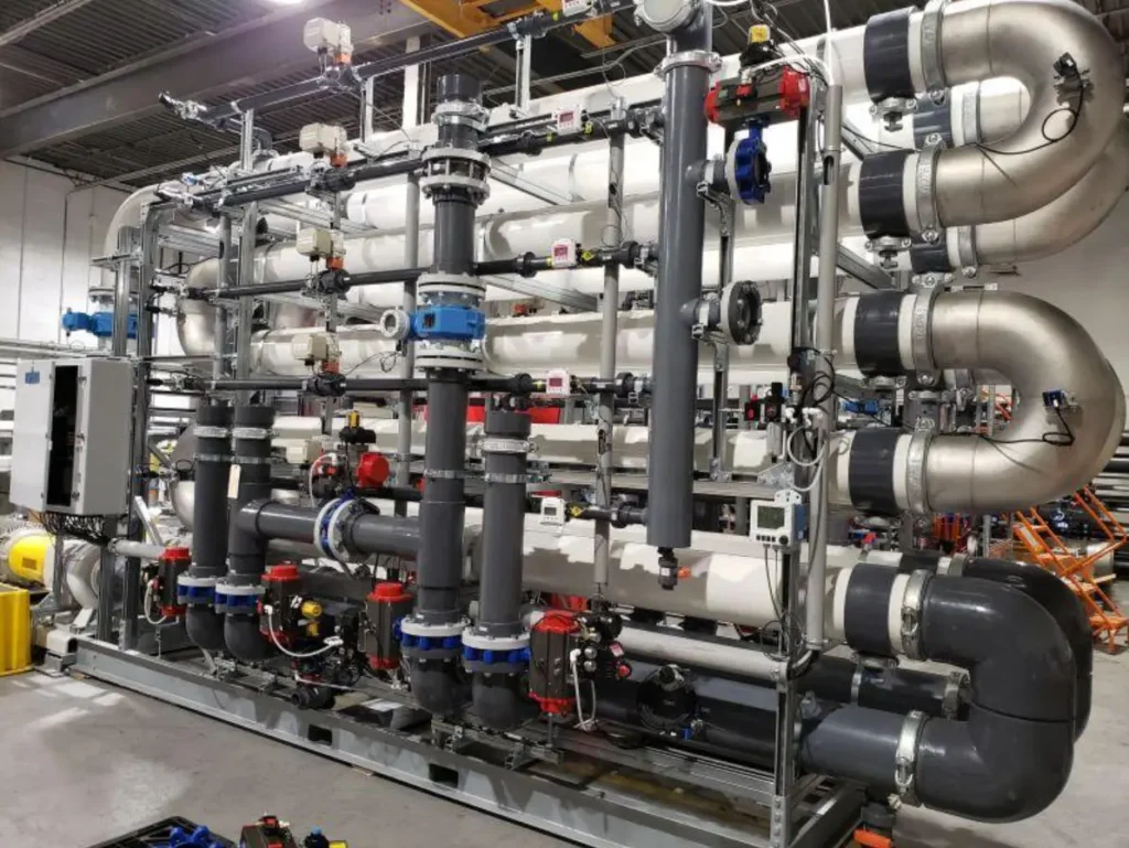
Tubular ultrafiltration membranes are used in landfill leachate treatment, particularly in external membrane bioreactor (TMBR) systems where high suspended solids concentrations require robust solid-liquid separation.
Leachate can contain high concentrations of organic matter, suspended solids, ammonia and other contaminants. Biological treatment processes may generate mixed liquor with a high suspended solids concentration.
In an external tubular membrane bioreactor (TMBR), the membrane unit separates treated liquid from biological solids.
The concentrated sludge is returned to the biological process, while the membrane permeate can undergo further treatment where required.
Typical process arrangement:
Biological Treatment → Circulation Pump → Tubular Membrane Unit → Permeate Collection → Further Treatment
The membrane provides a solid-liquid separation function; it does not independently guarantee the removal of dissolved salts, ammonia or all dissolved organic compounds.
Tubular Membrane Filtration for Oily Wastewater
Oily wastewater from machining, metal processing and other industrial operations may contain free oil, emulsified oil, suspended particles and cleaning chemicals.
Conventional gravity separation is generally more effective for free oil than for stable oil emulsions.
Tubular membrane filtration can be considered as part of a treatment process for separating selected emulsified contaminants and suspended matter.
Typical applications include the treatment of oily wastewater and spent metalworking fluids generated by machining and metal processing operations.
Important factors in membrane selection include:
Free oil versus emulsified oil
Oil concentration and emulsion stability
Presence of surfactants and cleaning chemicals
Operating temperature
Membrane fouling tendency
Cleaning requirements
Where wastewater contains a high concentration of free oil, upstream oil separation may be necessary to reduce membrane fouling.
The achievable permeate quality depends on the emulsion characteristics and selected membrane. A pilot test is recommended when the feed composition is uncertain.
Tubular Membrane Separation in Electroplating Wastewater Treatment
Electroplating wastewater may contain dissolved metal ions, suspended particles and chemical treatment residues.
In precipitation-based treatment processes, metal ions are converted into insoluble compounds through chemical reactions under controlled conditions.
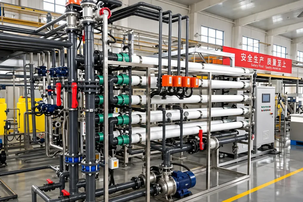
Tubular membrane filtration can then be used to separate the resulting precipitated solids from the treated liquid.
The application includes electroplating wastewater treatment systems using tubular membrane separation.
The role of the membrane is primarily to retain suspended precipitates and other particles. Dissolved metal ions that have not been effectively precipitated may pass through an ultrafiltration membrane.
Therefore, the upstream chemical treatment process, pH control and precipitation efficiency remain essential to achieving the required water quality.
Tubular UF Membrane Cleaning and Maintenance
Membrane fouling can result from the accumulation of suspended solids, organic substances, inorganic scale or other contaminants on the membrane surface and inside the flow channels.
Typical signs of membrane fouling include declining permeate flux, increasing operating pressure or abnormal hydraulic resistance.
Routine Operating Monitoring
Operators should monitor and record:
Feed and permeate flow rates
Feed, concentrate and permeate pressures
Operating temperature
Circulation flow
Permeate quality
Cleaning frequency and recovery performance
Membrane Cleaning
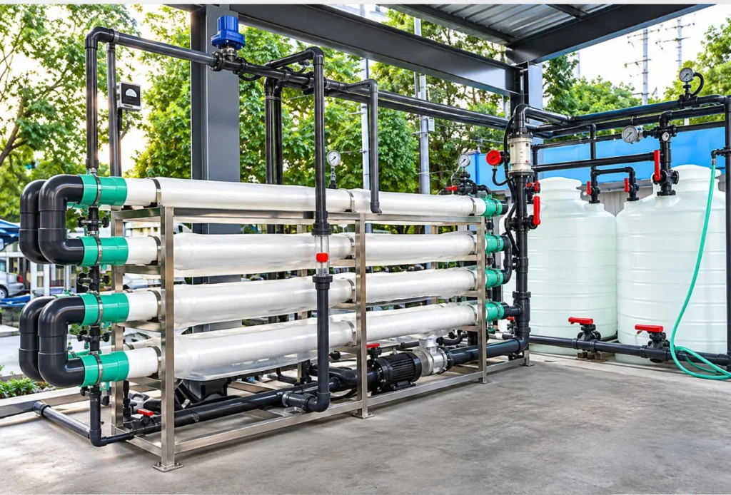
A typical tubular UF membrane cleaning procedure includes three main steps:
Water Flushing → Chemical Cleaning → Final Flushing
Chemical cleaning may involve acidic or alkaline solutions depending on the type of foulant and the membrane’s chemical resistance.
Cleaning chemicals, concentration, temperature, contact time and pH must be selected according to the specifications and chemical compatibility limits of the membrane model.
Incompatible chemicals or incorrect cleaning sequences can permanently damage the membrane.
Membrane Storage
When a tubular UF system is taken out of service, the membranes should be stored under the recommended preservation conditions for the specific membrane model.
Long-term storage without appropriate preservation can result in membrane deterioration or biological contamination.
| Operating symptom | Possible causes | Checks |
|---|---|---|
| Permeate flux declines | Fouling, temperature change | Normalize operating data, inspect fouling |
| Pressure drop increases | Channel blockage, solids accumulation | Check circulation flow and pressure |
| Permeate becomes turbid | Membrane or seal damage | Inspect seals and module integrity |
| Frequent cleaning required | Unsuitable pretreatment or flux | Review feed characteristics and operating conditions |
For additional guidance on membrane fouling and chemical cleaning, read our UF membrane cleaning procedure
Tubular UF Membrane Replacement for Existing Systems
Replacing an existing tubular membrane module requires both filtration-performance evaluation and mechanical compatibility verification.
A membrane with similar nominal surface area may not fit an existing system because of differences in module diameter, overall length, end connections, sealing arrangements or internal channel configuration.
For customers seeking Chinese-brand tubular UF membrane alternatives, Clear Environment provides product sourcing support, technical specification comparisons and replacement compatibility evaluations.
Mechanical compatibility
The following dimensions should be verified:
Overall module length
Housing outside diameter
End connection dimensions
Sealing and gasket arrangement
Feed, concentrate and permeate connections
Filtration compatibility
The comparison should also cover membrane material, filtration rating, active membrane area, operating pressure, temperature and chemical cleaning conditions.
Hydraulic compatibility
Differences in channel number, channel diameter and internal flow resistance can affect circulation pump requirements and system pressure losses.
A membrane should not be considered a direct replacement solely because it has the same nominal diameter or membrane area.
Customers may submit the existing module datasheet, drawings or photographs for a preliminary compatibility review.
For other UF replacement applications, explore our UF membrane replacement options. Tubular membrane compatibility must be evaluated separately based on module dimensions, connections and operating conditions
Source Tubular Ultrafiltration Membranes from China
Clear Environment works with water treatment distributors, engineering companies and system integrators sourcing tubular ultrafiltration membranes from China.
We offer tubular UF membrane sourcing, technical specification comparisons, product selection support and order coordination for water treatment distributors, engineering companies and system integrators.
For new installations, we can help evaluate available membrane configurations based on the required treatment capacity and operating conditions.
For replacement projects, we can coordinate dimensional comparisons and technical documentation to determine whether a suitable alternative is available.
Information Required for Quotation
For a new tubular UF membrane application, please provide:
Wastewater source and treatment objective
Required feed or permeate capacity
Available water analysis
Suspended solids concentration
Operating temperature and pH
Required permeate quality
Available membrane system configuration
For replacement orders, please provide the existing membrane model, quantity and technical drawings.
Request Technical Specifications & Quotation
Frequently Asked Questions
- Can tubular UF membranes operate with high suspended solids concentrations?
Tubular membranes are used in selected high-solids applications because their relatively large channels allow crossflow circulation. However, the acceptable solids concentration depends on feed viscosity, membrane channel size, circulation velocity and system design.
2. How do I choose between 6 mm, 8 mm and 12 mm membrane channels?
Channel selection involves balancing solids-handling capability, hydraulic pressure losses, membrane packing density and circulation energy. Larger channels may be advantageous for challenging feed liquids, but they do not automatically provide better overall system efficiency.
3. Can tubular UF membranes remove dissolved heavy metals?
Ultrafiltration membranes primarily separate suspended and colloidal materials. Dissolved metal ions generally require chemical precipitation or another suitable treatment process before membrane separation.
4. Can a tubular UF membrane with the same membrane area replace my existing module?
Not necessarily. Mechanical dimensions, end connections, membrane characteristics and hydraulic requirements must also be checked. Matching membrane area alone does not establish replacement compatibility.