
An EDI (Electrodeionization) system is normally operated after reverse osmosis (RO) and is designed to continuously remove ions from RO permeate to produce high-purity water. However, EDI performance can be affected by water quality, flow, pressure, electrical conditions, and operating procedures.
This electrodeionization troubleshooting guide summarizes several common EDI plant problems, their typical causes, symptoms, and recommended corrective measures.
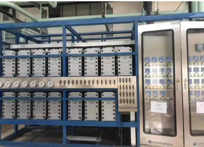
Oxidative Damage to the EDI Module
Possible Causes
Oxidizing substances may enter the EDI system from two main sources:
- Oxidizing substances naturally present in the feed water.
2. Oxidants added during pretreatment for disinfection, or oxidative substances generated during UV disinfection.
Typical Symptoms
Oxidation can damage and break down the ion exchange resin inside the EDI module. The broken resin may block the internal flow channels, causing the EDI system capacity to gradually decrease.
Typical symptoms include:
- Increasing pressure drop across the EDI module
- Decreasing flow rate or production capacity
- Gradual deterioration in product water quality
- Chemical cleaning has little or no effect
- The problem develops gradually rather than suddenly
Because oxidative damage to the resin is not normally reversible through chemical cleaning, continued operat
Recommended Measures
A reducing agent should be dosed before the first-stage RO inlet to control the oxidation-reduction potential (ORP). As a general operating guideline, the feed ORP should preferably be controlled at ≤200 mV.
A UV disinfection unit should not be installed directly on the EDI feed-water side, as oxidative effects associated with UV operation may adversely affect the EDI resin.
Operating data should be recorded regularly. If EDI performance shows a continuous decline, the problem should be investigated and corrective action taken as early as possible.
ORP should be used as a reference rather than the only basis for judgment, because ORP instruments have measurement accuracy limitations.
Recommended Operating Records
The following operating parameters should be recorded at least once per day.
| No. | Parameter | Unit |
|---|---|---|
| 1 | Fresh water inlet pressure | psi, Bar |
| 2 | Concentrate inlet pressure | psi, Bar |
| 3 | Fresh water product pressure | psi, Bar |
| 4 | Concentrate discharge pressure | psi, Bar |
| 5 | Electrode water outlet pressure | psi, Bar |
| 6 | Concentrate discharge flow | psi, Bar* |
| 7 | Concentrate flow | gpm, m³/h |
| 8 | Electrode water flow | gpm, m³/h |
| 9 | Fresh water flow | gpm, m³/h |
| 10 | Rectifier voltage | V |
| 11 | System current | A |
| 12 | Product water resistivity | MΩ·cm |
| 13 | Concentrate conductivity | μS/cm |
| 14 | Inlet water conductivity | μS/cm |
| 15 | Product water temperature | ℉, ℃ |
The following additional parameters should be recorded at least once per week.
| No. | Parameter | Unit |
|---|---|---|
| 1 | Inlet water hardness | ppm |
| 2 | Inlet water carbon dioxide (CO₂) | ppm |
| 3 | Inlet water silica (SiO₂) | ppm |
EDI Module Burnout Due to Insufficient Water Flow
Possible Cause
EDI removes ions through an electrically driven process, which generates a certain amount of heat during normal operation. If the EDI module is energized without sufficient water flow, localized overheating can occur and may permanently damage or burn out the module.
Typical Symptoms
This type of failure usually develops very quickly. Typical symptoms include:
- Abnormally high or low EDI current
- Abnormal voltage readings
- The EDI module cannot be energized
- Product water quality may deteriorate
Recommended Measures
The EDI module should never be energized without adequate water flow.
Flow protection and alarms should be provided for all three water streams:
- Product water (dilute water)
- Concentrate water
- Electrode water
If automatic protection is not installed, the operator must manually check the valve positions and confirm that the required flow rates are available before switching on the EDI power supply.
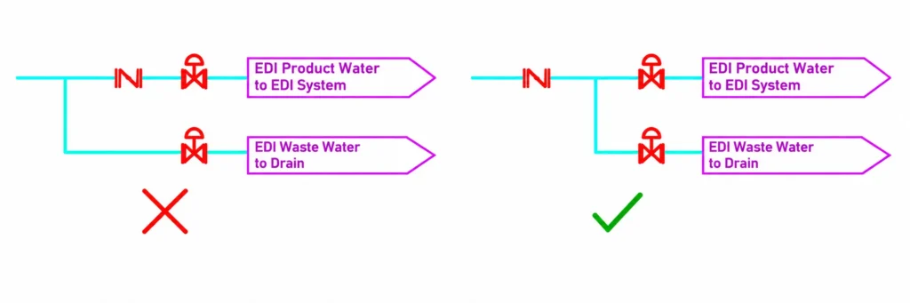
Important Note on Reject/Drain Piping
The reject/drain line for off-specification product water should be controlled by a flow-regulating valve in the same way as the product-water line.
Otherwise, when the system switches to reject or drain mode, changes in the hydraulic resistance may cause the concentrate-water and electrode-water flow rates to decrease, creating a potential risk to the EDI module.
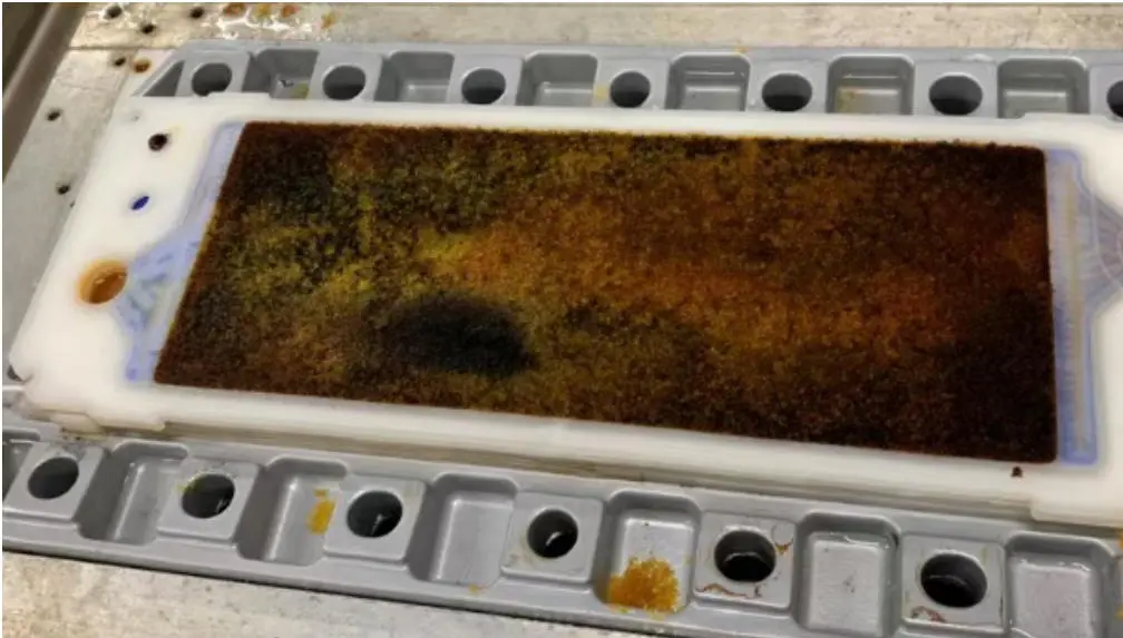
EDI Module Fouling or Flow Restriction
EDI module fouling can generally be divided into two categories: scaling or organic fouling and physical blockage on the feed-water side.
Scaling or Organic Fouling
Possible Causes
Common causes include:
- Fluctuations in feed-water quality
- Reduced RO membrane salt rejection
- Failure to use a two-pass RO process when required
- Bacterial growth caused by prolonged system shutdown
Typical Symptoms
Fouling usually develops gradually and may cause:
- Decreasing EDI production capacity
- Increasing pressure drop
- Increasing feed pressure
- Possible deterioration in product water quality
Unlike oxidative resin damage, scaling and organic fouling can often be improved through appropriate chemical cleaning.
Recommended Measures
Chemical cleaning should be carried out when fouling is confirmed.
The feed-water quality and RO membrane performance should also be checked regularly to determine whether the RO membranes need cleaning or replacement.
If the system will remain shut down for an extended period, fresh water should be introduced periodically as appropriate to reduce the risk of bacterial growth.
Important Note
EDI fouling should not be diagnosed based on flow rate alone. Both pressure and flow should be considered.
For example, in an EDI system with constant product-water flow control, the flow rate may remain unchanged even when fouling is developing. A significant increase in pressure drop or feed-water pressure can therefore be an early indication of internal fouling.
Physical Blockage on the Feed-Water Side
Possible Cause
A common cause is failure to properly flush the feed-water piping before commissioning a new EDI system.
Construction debris, particles, pipe scale, or other foreign matter may enter the EDI module and restrict the internal flow channels.
Typical Symptoms
Physical blockage generally occurs shortly after commissioning and may cause:
- A rapid decrease in EDI production capacity
- Reduced flow through the module
- Product water quality usually remains relatively normal
This helps distinguish physical blockage from some other types of EDI problems.
Recommended Measures
The affected EDI module can be backwashed to remove the blockage.
The backwash pressure should not exceed 0.2 MPa.
The backwash water quality should meet the required EDI feed-water specifications.
Before commissioning a new system, the entire feed-water piping should also be thoroughly flushed to prevent construction debris from entering the EDI modules.
EDI Feed Water Meets the Requirements, but Product Water Quality Is Not Acceptable
Sometimes the EDI feed-water quality, system capacity, and electrical current/voltage all appear to be normal, but the product-water conductivity remains above the required level.
Several possible causes should be checked.
Positive and Negative Poles Are Reversed
Typical Symptoms
If the positive and negative electrical connections are reversed, the affected EDI module may show a significant increase in product-water conductivity after the power is switched on.
Interestingly, the product water may show better quality when the module is not energized.
The current and voltage readings may still appear normal, making this problem easy to overlook.
Recommended Measure
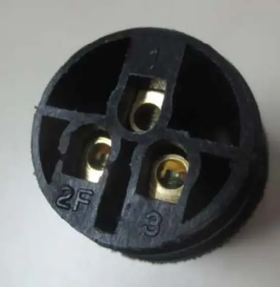
Check the DC power supply polarity and correct the electrical connections.
For the relevant power connector, the wiring arrangement is:
1 – Ground
2 – Positive (+)
3 – Negative (-)
The exact wiring should always be checked against the EDI module manufacturer’s electrical diagram before energizing the system.
Incorrect Pressure Settings
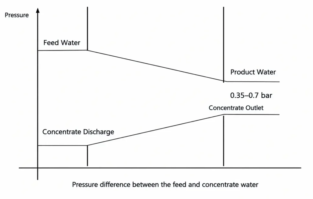
For E-CELL EDI modules, the pressure relationship between the dilute/product-water side and concentrate-water side is important during commissioning.
The concentrate-water inlet pressure should be set approximately 0.35–0.7 bar lower than the dilute-water outlet pressure, so that the dilute-water pressure remains higher than the concentrate-water pressure throughout the process.
When the Pressure Difference Cannot Be Achieved
This may happen when:
- The concentrate-water piping is undersized
- The pump head is insufficient
A higher concentrate-water inlet pressure is required simply to maintain the required concentrate flow
Recommended Measures
As a general recommendation, the EDI feed-water pressure on the dilute side should reach approximately 4 bar, and the piping diameter should be selected appropriately according to the required flow rate and pressure conditions.
The Effect of Carbon Dioxide (CO₂)
EDI feed-water pH should generally be maintained at approximately 7–7.5.
If the feed water is too acidic, a certain amount of dissolved carbon dioxide may remain in the water and pass through the RO process. In the EDI process, CO₂-related species can form bicarbonate ions, which may affect product-water quality.
Lorem ipsum dolor sit amet, consectetur adipiscing elit. Ut elit tellus, luctus nec ullamcorper mattis, pulvinar dapibus leo.
Recommended Measure
For a two-pass RO system, caustic soda can be dosed before the second-pass RO to increase the pH to approximately 8–9.
At a higher pH, dissolved CO₂ is converted into ionic forms, which can then be more effectively removed by the RO membrane and subsequently by the EDI system.
Important Note
Carbon dioxide is relatively soluble in water. Rainwater can absorb CO₂ from the atmosphere while falling, resulting in a natural pH of approximately 5.6.
Therefore, installing a degasser or CO₂ removal unit directly after the first-stage RO may not always provide the expected improvement. The actual raw-water chemistry and RO process should be evaluated before selecting a CO₂ removal method.
EDI Module May Require Enhanced Current Regeneration
An EDI module may require a temporary increase in operating current after:
- Chemical cleaning
- Extended shutdown
- A period of operation with water flow but without power
Under these conditions, the module may not immediately return to its normal product-water quality.
Recommended Measure
After confirming that all required water flows are normal, temporarily increase the EDI operating current to approximately 3–4 A.
Once the product-water quality returns to the required level, gradually reduce the current back toward the normal operating range.
The actual current setting should always remain within the manufacturer’s specified operating range for the particular EDI module.
Conclusion
Most EDI plant problems can be identified by looking at several operating parameters together rather than relying on a single reading.
When troubleshooting an EDI system, it is important to monitor:
- Feed-water quality
- RO permeate conductivity
- pH and ORP
- Product-water conductivity
- Product, concentrate, and electrode-water flow
- Feed and outlet pressures
- Pressure drop across the EDI module
- DC current and voltage
- Operating history and shutdown records
Regular data recording is particularly important because some EDI problems, such as oxidative resin damage and fouling, develop gradually.
If an EDI system shows a continuous decline in production capacity or product-water quality, the cause should be investigated promptly. Comparing current operating data with historical records is often one of the most effective ways to identify abnormal trends before permanent damage occurs.