
Article Outline
This article walks through how ordinary tap water is gradually purified into 18.2 MΩ·cm ultrapure water used in semiconductor fabs, laboratories, pharmaceuticals, and precision manufacturing.
Main process sections include:
- Pretreatment
- Multimedia filtration
- Activated carbon dechlorination
- Water softening or antiscalant dosing
- Security cartridge filtration
- Reverse Osmosis (RO)
- Polyamide membrane separation mechanism
- Single-pass vs double-pass RO
- Removal limits for silica, boron, and dissolved gases
- Membrane Degassing
- CO₂ removal principles
- Conductivity reduction after degassing
- Dissolved oxygen control
- EDI (Electrodeionization)
- Ion migration under electric field
- Continuous self-regeneration
- Why EDI replaced traditional mixed beds in many systems
- UV Oxidation
- 185 nm hydroxyl radical oxidation
- 254 nm microbial control
- TOC reduction mechanisms
- Polishing Mixed Bed
- Final ion exchange polishing
- Silica and boron removal
- Achieving stable 18.2 MΩ·cm ultrapure water
- Final Filtration and Distribution Loop
- Point-of-use ultrafiltration
- High-purity piping materials
- Recirculation loop design
- Online monitoring and contamination control
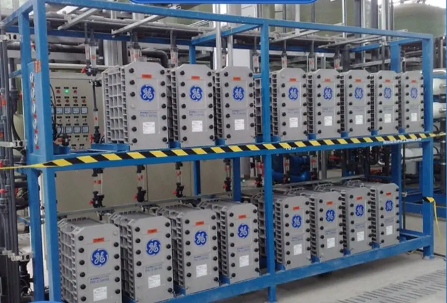
Turning ordinary city water into 18.2 MΩ·cm (25°C) Ultrapure Water is basically a process of removing almost everything dissolved, suspended, living, or floating in it. Salts, organics, particles, bacteria, dissolved gases — all pushed down close to ppt-level contamination.
No single machine can do that alone. In practice, an ultrapure water system is a chain of barriers. Every stage exists because the previous stage still leaves something behind.
Pretreatment
Raw tap water is rough on downstream membranes. Sand, colloids, free chlorine, hardness — any of these can shorten RO membrane life very quickly.
Multimedia Filter — Deep Bed Particle Capture
Inside the vessel, anthracite and quartz sand are layered from coarse to fine.
As water flows downward, larger particles get trapped in the upper layers first. Finer particles move deeper into the bed and are captured by smaller pore spaces, surface forces, and Brownian motion effects.
This is not surface filtration. The contaminants penetrate into the filter depth, so dirt holding capacity is much higher than a simple cartridge filter.
After 24–72 hours of operation, the bed is backwashed. Water flows upward, the media expands and fluidizes, and the trapped solids are flushed out.
Activated Carbon Filter — Chlorine Removal Is Not Just Adsorption
Activated carbon works especially well because of its transitional pore structure, typically around 2–50 nm.
For free chlorine removal, the mechanism is partly catalytic, not only physical adsorption.
C+2Cl2+2H2O→C++4H++4Cl−+CO2↑C + 2Cl_2 + 2H_2O \rightarrow C^{+} + 4H^{+} + 4Cl^{-} + CO_2\uparrowC+2Cl2+2H2O→C++4H++4Cl−+CO2↑
Oxygen-containing functional groups on the carbon surface help decompose hypochlorous species into chloride ions.
At the same time, the huge surface area — often above 1000 m²/g — adsorbs part of the natural organic matter before it reaches the RO section. That matters, because organic fouling on RO membranes is difficult to reverse once it starts.
Softener or Antiscalant Dosing
If a softener is used, it normally contains sodium-form strong acid cation resin.
Calcium and magnesium ions exchange with sodium ions attached to the resin:
2R−Na+Ca2+→R2−Ca+2Na+2R{-}Na + Ca^{2+} \rightarrow R_2{-}Ca + 2Na^{+}2R−Na+Ca2+→R2−Ca+2Na+
Once the resin is exhausted, brine regeneration pushes the hardness ions back off the resin.
Some systems skip softening and use antiscalants instead. These chemicals work through threshold inhibition and crystal distortion mechanisms. Tiny amounts of phosphonate-based antiscalant adsorb onto microcrystal surfaces and stop calcium carbonate crystals from growing into actual scale.
So even though the concentrate side becomes supersaturated, precipitation is delayed.
Security Filter — Last Mechanical Barrier
Usually this is a 5 μm melt-blown polypropylene cartridge filter.
Simple job. Catch anything that escaped upstream. Small particles, media fragments, pipe debris.
Because once particles hit the polyamide RO membrane surface, scratches and irreversible fouling can happen very quickly.
Reverse Osmosis
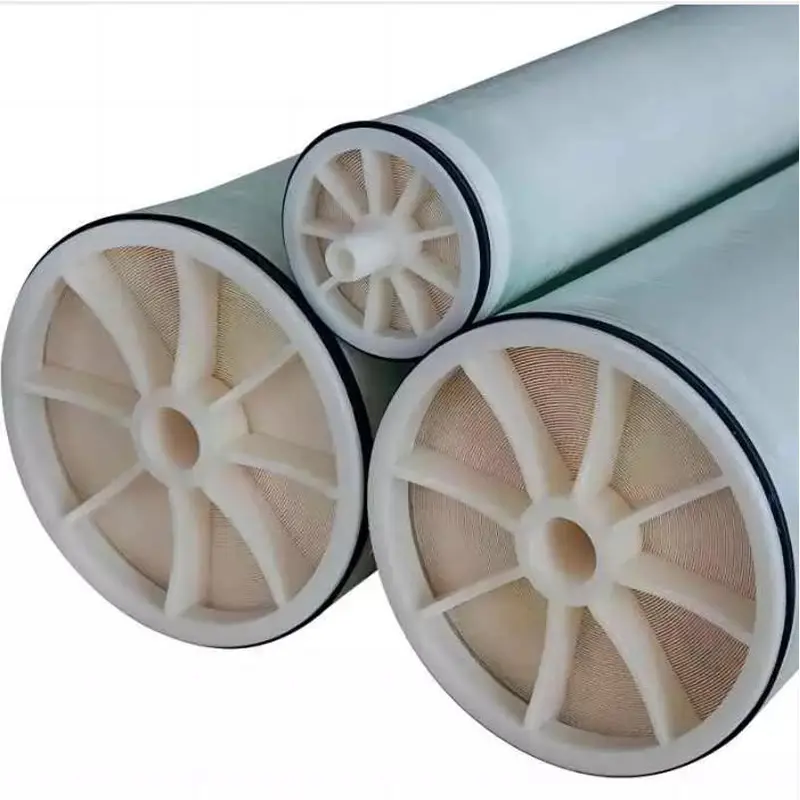
Reverse osmosis is the core desalination step of the entire ultrapure water train. It determines the basic ionic quality of the water.
Membrane Structure
Most systems use aromatic polyamide composite spiral-wound membranes.
The structure is layered:
- nonwoven support layer
- porous polysulfone layer
- ultrathin dense polyamide selective layer, roughly 0.2 μm thick
The polyamide surface contains carboxyl and amine groups. In water, the membrane surface becomes negatively charged.
Separation Mechanism — Solution-Diffusion Dominates
Water molecules dissolve into the membrane and diffuse across under pressure.
Salt ions behave differently. Their hydrated radius and electrostatic effects reduce both solubility and diffusion rate inside the membrane.
Typical rejection:
- monovalent ions like Na⁺ and Cl⁻: around 98–99%
- divalent ions like Ca²⁺ and SO₄²⁻: often above 99.5%
But RO is weaker against dissolved gases and weakly ionized species.
CO₂, boric acid, and silicic acid can partially pass through because they exist mainly in molecular form, especially near neutral pH.
That is why silica and boron usually become the “last difficult contaminants” in an ultrapure water system.
Single-Pass vs Double-Pass RO
Single-pass RO permeate conductivity is commonly around 5–30 μS/cm.
There are still residual sodium, bicarbonate, dissolved CO₂, silica, and trace ions present.
In double-pass RO, first-pass permeate feeds a second RO stage directly. Final conductivity can drop below 2 μS/cm consistently.
Most colloids and large organic molecules are already removed at this point.
But dissolved CO₂ becomes relatively concentrated on the permeate side because RO membranes do not effectively reject gases. So conductivity may still look artificially high.
That is usually where degassing comes in.
Membrane Degassing
Dissolved CO₂ forms carbonic acid in water:
CO2+H2O⇌H2CO3⇌H++HCO3−CO_2 + H_2O \rightleftharpoons H_2CO_3 \rightleftharpoons H^{+} + HCO_3^{-}CO2+H2O⇌H2CO3⇌H++HCO3−
Even small amounts can increase conductivity noticeably.
More importantly, bicarbonate becomes an ionic load for downstream EDI and polishing resin.
Membrane degassers typically use hydrophobic polypropylene or PTFE hollow fiber membranes.
Water flows inside the fibers. Vacuum or high-purity nitrogen is applied outside.
Driven by partial pressure difference under Henry’s Law, CO₂ diffuses through the membrane wall and gets removed.
Degassing efficiency can exceed 99%.
RO permeate conductivity may drop from around 2 μS/cm to below 1 μS/cm after proper degassing.
Dissolved oxygen removal is another side benefit. Less oxidation, less microbial growth risk in the loop.
Electrodeionization (EDI)
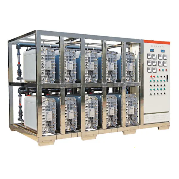
Electrodeionization is basically continuous ion exchange combined with electrodialysis.
It replaced traditional mixed beds in many modern ultrapure water systems because it operates continuously without chemical regeneration.
Internal Structure
Inside the EDI stack, cation and anion exchange membranes alternate repeatedly, forming dilute chambers and concentrate chambers.
The dilute chambers are filled with mixed ion exchange resin, creating conductive pathways.
A DC electric field is applied across the stack.
- cation membranes allow only positive ions through
- anion membranes allow only negative ions through
Ion Removal Process
Residual ions like Na⁺, Cl⁻, and Ca²⁺ first exchange onto the resin.
Then the electric field pulls them off the resin continuously:
- cations migrate through cation membranes
- anions migrate through anion membranes
Both end up in the concentrate stream and are flushed away.
The resin dramatically improves conductivity inside the dilute chamber, making ion migration much more efficient than electrodialysis alone.
Water Splitting and Self-Regeneration
As ion concentration becomes extremely low, local electrical resistance increases sharply.
Under a strong enough voltage gradient, water splitting occurs at resin contact points and membrane interfaces:
H2O→H++OH−H_2O \rightarrow H^{+} + OH^{-}H2O→H++OH−
The generated H⁺ and OH⁻ continuously regenerate the ion exchange resin in place.
No acid or caustic regeneration chemicals needed.
EDI product water typically reaches 17.5–18 MΩ·cm resistivity steadily.
Still, traces of silica, boron, and low molecular weight organics may remain. TOC may still sit around 20–50 ppb.
So one more polishing stage is usually needed.
UV Oxidation
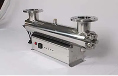
For true ultrapure water, TOC requirements are extremely strict.
In semiconductor or advanced analytical applications, TOC often needs to stay below 5 ppb, sometimes below 1 ppb.
185 nm UV — Hydroxyl Radical Generation
Low-pressure mercury lamps emit mainly at 185 nm and 254 nm.
The 185 nm wavelength has enough photon energy to split water and generate hydroxyl radicals.
These radicals are extremely aggressive oxidizers.
They attack trace organics continuously — plasticizer leachates, bacterial metabolites, additives, residual organics from upstream components — eventually mineralizing them into CO₂ and water.
254 nm UV — Microbial Control
254 nm UV damages microbial DNA and RNA directly.
It also helps place some organic molecules into excited states, making them easier targets for hydroxyl radical oxidation.
The resulting CO₂ and weak acids are later removed by polishing resin or downstream degassing.
Nuclear-Grade Polishing Mixed Bed
Even after EDI, the water is not yet at the theoretical purity limit.
To consistently achieve 18.2 MΩ·cm ultrapure water, final polishing mixed beds are still widely used.
Why Mixed Bed Works Better
If separate cation and anion beds are used individually, equilibrium limitations become noticeable at trace ion levels.
In a mixed bed, cation and anion resins are intimately mixed together.
The H⁺ released by cation resin and the OH⁻ released by anion resin immediately combine into water:
H++OH−→H2OH^{+} + OH^{-} \rightarrow H_2OH++OH−→H2O
That continuously drives the ion exchange equilibrium toward complete removal.
Residual ion concentration can drop into the ng/L range, and resistivity climbs to the theoretical 18.2 MΩ·cm limit almost immediately.
Final Silica and Boron Removal
Silica exists mainly as weakly ionized silicic acid.
Inside strong base anion resin, the local high-OH⁻ environment converts it into exchangeable ionic form:
R−OH+H3SiO4−→R−H3SiO4+OH−R{-}OH + H_3SiO_4^{-} \rightarrow R{-}H_3SiO_4 + OH^{-}R−OH+H3SiO4−→R−H3SiO4+OH−
Boron removal follows a similar mechanism.
This is one area where polishing resin still performs better than EDI alone.
Nuclear-Grade Resin Matters
The polishing resin itself must be extremely clean.
Nuclear-grade mixed bed resin has:
- very low TOC leaching
- narrow particle size distribution
- complete ionic conversion
- minimal extractables
Otherwise the resin itself becomes a contamination source.
Final Filtration and Distribution Loop
Ironically, once water becomes ultrapure, it also becomes chemically aggressive and easy to contaminate again.
At this stage, even the piping system becomes part of the purification process.
Point-of-Use Microfiltration / Ultrafiltration
Near the use point, systems often install 0.1 μm or 0.04 μm absolute-rated PTFE or polysulfone filters.
These capture:
- resin fines
- bacterial fragments
- endotoxins
- ultrafine particles
In life science applications, endotoxin control is critical.
Particle counts above 0.05 μm may need to stay below 1 particle/mL.
Loop Design and Materials
Distribution piping is usually made from high-purity PVDF, PFA, or electropolished 316L stainless steel.
Dead legs are unacceptable.
Any stagnant area becomes a bacterial growth zone and an ion contamination source.
That is why ultrapure water loops are designed as continuously recirculating systems.
Typical loop velocity stays around 1.5–2 m/s to maintain turbulent flow and suppress biofilm formation.
The water continuously returns to the storage tank or purification section for reprocessing.
Online Monitoring
A proper ultrapure water loop is heavily monitored.
Typical instruments include:
- resistivity meter with 25°C temperature compensation
- online TOC analyzer
- particle counter
- flow meter
Small resistivity drops or TOC increases are usually detected long before operators can see any visible issue.
Many systems automatically switch into internal recirculation or sanitization mode until water quality recovers.
Related Articles
- Advantages and Disadvantages of Electrodeionization vs Ion Exchange
- Why Does an EDI Water Treatment System Require Ventilation During Operation?
- Electrodeionization EDI System Design Guide: 20 Practical Tips to Avoid Common Design Mistakes
- Electrodeionization Troubleshooting: Common EDI Plant Problems and Solutions