
Reverse osmosis is an advanced, highly efficient, and relatively energy-saving separation technology. Using reverse osmosis membranes to separate solutes from solvents has become a mature water treatment technology. According to different water qualities, appropriate reverse osmosis membranes are selected to ensure that the produced water meets the requirements of the Drinking Purified Water Quality Standard (CJ94-2005).
At present, reverse osmosis technology has been widely applied in water treatment systems. This article introduces a 0.5 t/h small reverse osmosis pure water production system, which can be used in office drinking water supply, laboratory pure water preparation, pharmaceutical, food, electronics, biotechnology, and chemical fiber industries.
Design of the reverse osmosis plant process
Pretreatment Process
The small water purification reverse osmosis plant process adopts a “pretreatment + reverse osmosis” configuration. The pretreatment system includes a multimedia filter and an ultrafiltration filter. Effective pretreatment can significantly extend the service life of reverse osmosis membranes, and the final water quality of the reverse osmosis system largely depends on the pretreatment performance.
Figure 1 illustrates the water purification reverse osmosis plant process. As shown in Figure 1, tap water first passes through a water inlet valve and enters the raw water tank, where the pretreatment stage begins. A pump transfers raw water into the multimedia filter containing quartz sand and activated carbon. Quartz sand removes suspended particles, while activated carbon removes residual chlorine, chemical contaminants, heavy metals, and other impurities. The multimedia filter requires periodic backwashing, and the backwash water enters the concentrate treatment system.
After multimedia filtration, the water enters the ultrafiltration filter, which effectively removes particles, colloids, bacteria, pyrogens, and organic matter. Solute molecules larger than the membrane pore size are retained by the ultrafiltration membrane. The ultrafiltration unit also requires backwashing, and both the backwash water and concentrate are discharged into the concentrate treatment system, completing the pretreatment process.
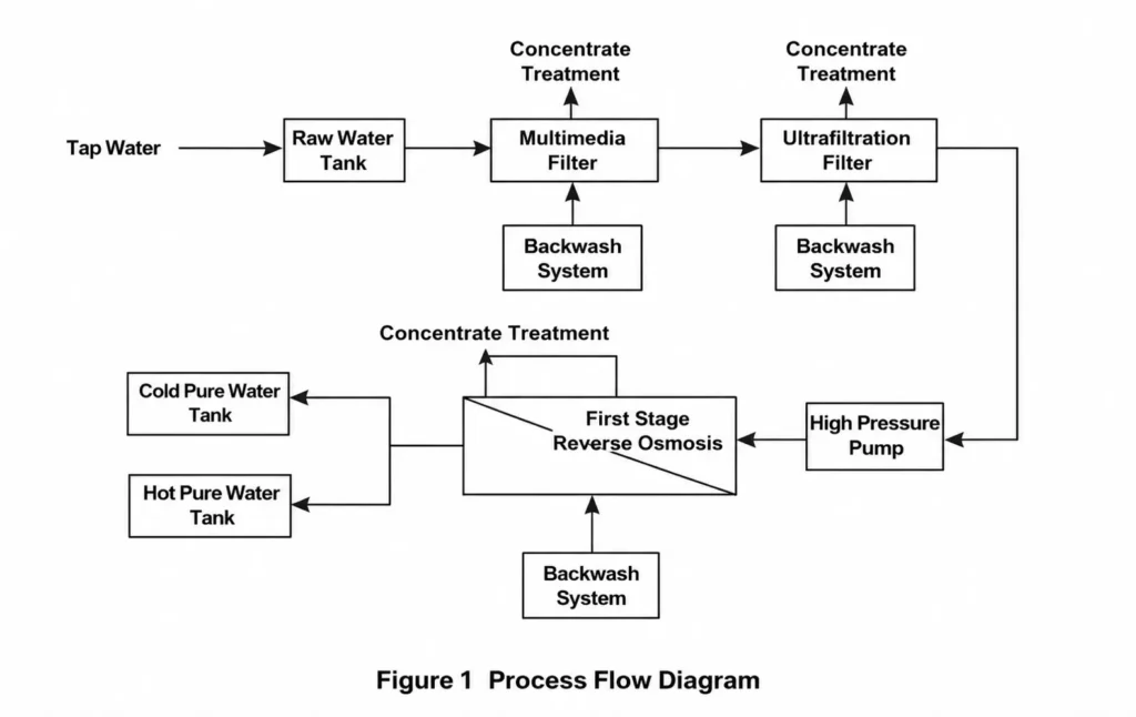
A high-pressure pump then delivers the pretreated water into the reverse osmosis system, where contaminants such as bacteria, viruses, and heavy metal ions are removed. After the reverse osmosis process, part of the permeate enters a cold pure water tank for ambient-temperature water supply, while another portion is electrically heated and stored in a hot pure water tank. All materials in contact with the reverse osmosis permeate are sanitary-grade materials.
Theoretically, reverse osmosis membranes can completely remove microorganisms from tap water. However, during actual operation, bacteria may grow when the system stops operating. Therefore, ultraviolet sterilization lamps are installed inside the cold and hot pure water tanks to ensure sterile and non-toxic drinking water.
Backwash System
During normal operation of the reverse osmosis system, feed water and concentrate flow across the membrane surface at a certain velocity, making it difficult for contaminants to deposit. However, when the system stops operating, pollutants can quickly accumulate on the membrane surface and foul the membrane elements.
Therefore, the reverse osmosis plant process includes a backwash system that uses reverse osmosis permeate to flush the membrane surface during shutdown, preventing secondary contamination.
If no new water production cycle begins within four hours, the PLC control system automatically initiates timed flushing. The PLC opens the switching valve and automatic flushing valve, using tap water pressure to flush the reverse osmosis membrane automatically for 30 seconds.
Concentrate Water Treatment
The concentrate requiring treatment includes reverse osmosis reject water, as well as backwash water from the multimedia filter, ultrafiltration filter, and reverse osmosis system. This wastewater is directed into a concentrate multimedia filter where flocculants are added. The dosage of flocculants is determined through preliminary testing according to water quality conditions.
In this designed system, concentrate water is treated by adding flocculants, and the treated water is returned to the raw water tank to improve overall recovery efficiency.
To maximize water utilization, treated concentrate water can also be reused as industrial process water, such as:
- Backwash water for filtration units,
- Dust suppression water,
- Cooling water,
- Ash flushing,
- Slag flushing,
- Road spraying,
- Landscaping irrigation,
- Toilet flushing,
- Vehicle washing,
- Workshop floor cleaning,
- And construction water.
If the treated wastewater meets regulatory standards and is approved by municipal wastewater treatment facilities, it may also be discharged into municipal sewage networks.
Control System
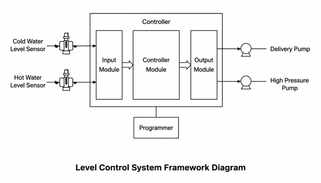
When the water level indicators in the cold or hot pure water tanks reach the low-level position, the PLC control system activates the inlet valve and transfer pumps. Tap water then passes through the multimedia filter and ultrafiltration filter for pretreatment. A high-pressure pump subsequently transfers the pretreated water into the reverse osmosis membrane system.
The control system uses a PLC controller with feedback control logic to regulate water levels, as shown in Figure 3.
The PLC is connected to sensor input modules and pump output modules. The input module continuously collects water level data from the cold and hot water tanks using level sensors.
When water levels fall below the low-level setting, the PLC sends control signals to start the pumps and refill the tanks. When water levels exceed the high-level setting, the PLC stops the pumps to maintain stable water levels within the specified range.
The conductivity of the final product water is used to evaluate the purification performance of the system. Based on conductivity data, the PLC adjusts valves and pump frequency converters to ensure that the filters and reverse osmosis system operate under optimal conditions. The conductivity data can also be used to determine whether membrane replacement is necessary.
Main Equipment Selection
Reverse Osmosis Membranes
The selection of reverse osmosis membranes is critical. Based on comprehensive considerations, 8040 membrane elements are generally suitable for reverse osmosis systems with capacities above 5 t/h, while 4040 membrane elements are more suitable for systems below 3 t/h. Systems between 3–5 t/h may use either 8040 or 4040 membrane elements.
Membrane selection depends on raw water quality and user design requirements. Key reference parameters include:
- Membrane salt rejection rate,
- Permeate flow rate,
- And recovery rate.
These characteristics are determined during membrane manufacturing.
Considering these factors, the selected membrane configuration consists of two BW30-LCLE 4040 membrane elements manufactured by DuPont, installed in pressure vessels with an inner diameter of 101 mm.
High-Pressure Pump
The actual operating pressure of membrane elements is influenced by factors such as:
- Ambient temperature,
- Average water flux,
- Feed salinity,
- System recovery rate,
- And membrane type.
The designed operating pressure of the reverse osmosis membrane system is 0.6 MPa. However, because membrane flux gradually declines over time, a higher-head high-pressure pump is selected to ensure sufficient pressure margin after three years of operation.
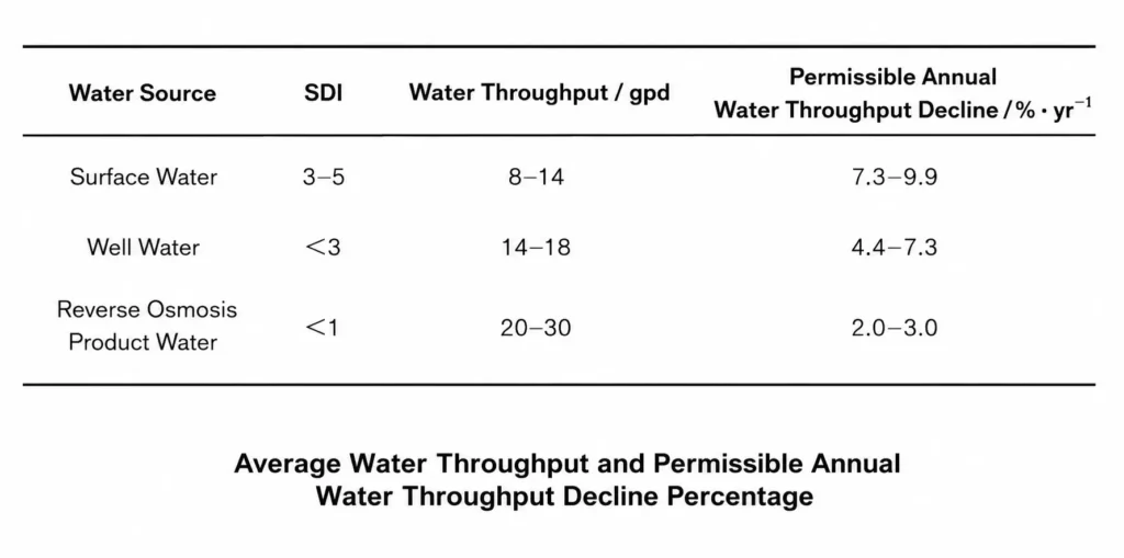
According to Table 1, assuming a maximum annual flux decline of 9.9% and a working pressure of 0.6 MPa, the relationship between pressure and water flux remains positively correlated within a certain range. Based on a 10% annual decline assumption, the selected high-pressure pump should provide a head of at least 78 m to maintain the design permeate capacity after three years.
Multimedia Filter
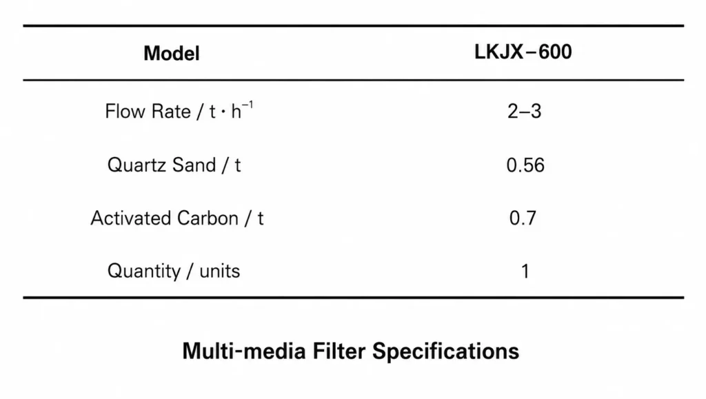
The multimedia filter reduces suspended solids and colloidal matter in reverse osmosis feed water. Filter media selection is very important because different media provide different functions.
Based on raw water quality, a dual-media filtration configuration combining quartz sand and activated carbon is selected. The upper layer uses larger-particle, lower-density quartz sand to improve dirt-holding capacity and reduce head loss increase. The lower layer uses smaller-particle, higher-density activated carbon to enhance adsorption performance.
Ultrafiltration Filter
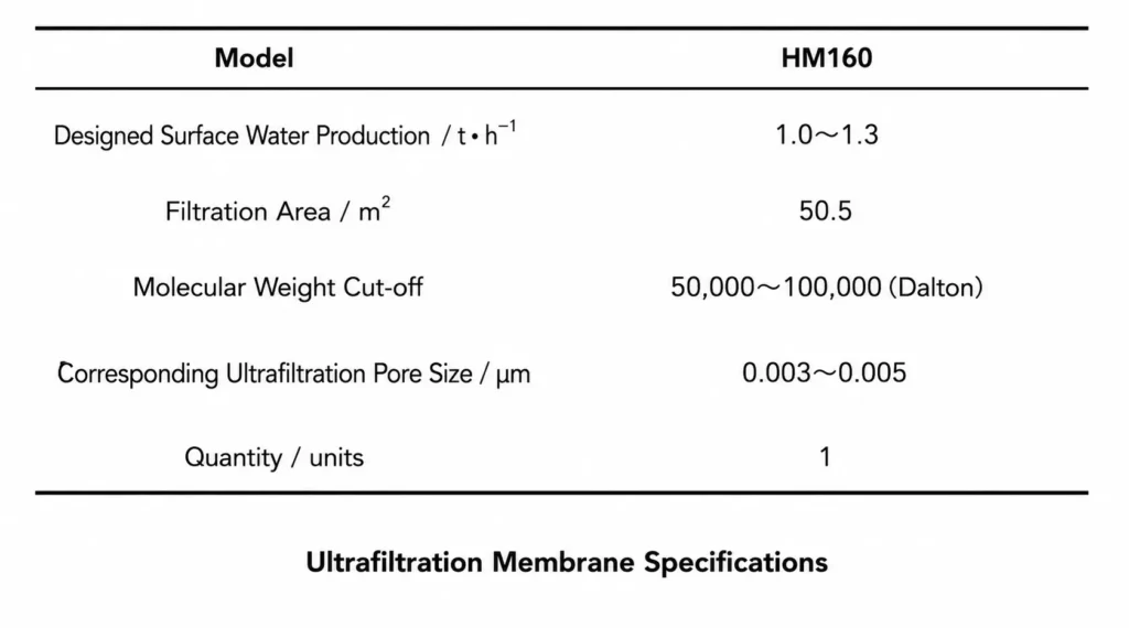
Ultrafiltration systems are highly effective for removing particles, colloids, bacteria, pyrogens, and organic substances from water. They are essential equipment in water treatment engineering and material separation applications. The ultrafiltration membrane parameters are listed below.
Calculation and Selection of the reverse osmosis plant process
Reverse Osmosis Membrane Configuration
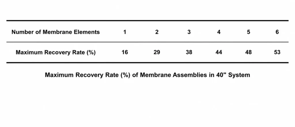
- The selected reverse osmosis membrane model is BW30-LCLE 4040, with a permeate capacity of 0.25 t/h per membrane element. Therefore, two membrane elements are sufficient to meet the required production capacity.
- the overall system recovery rate is 29%,
- and the recovery rate of a single membrane is 16%.
Two membrane arrangement methods are considered:
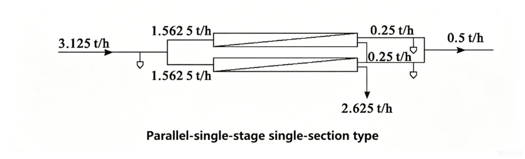
Parallel Arrangement — Single Stage, Single Pass
As shown in Figure 4, the actual recovery rate is 16%.
- Series Arrangement — Single Stage, Two Passes
As shown in Figure 5, the actual recovery rate is 29.4%.
To ensure a permeate production rate of 0.5 t/h: - the feed flow for the parallel arrangement is 3.125 t/h,
- while the feed flow for the series arrangement is 1.7 t/h.
After comparison, the series arrangement is selected because it improves recovery efficiency when the design permeate capacity requirement is relatively low.
Hydraulic Resistance Calculation of the RO Piping System
- In principle, the optimal pipe diameter can be determined by comparing different flow velocities and selecting the most economical and practical design. For workshop piping systems, flow velocity is typically selected empirically within an economic range, and the pipe diameter is calculated according to mass conservation equations.
Flow resistance mainly consists of: - Friction loss in straight pipes,
- And local resistance losses caused by elbows, valves, and fittings.
In this design: - Permeate production capacity is 0.5 t/h,
- Reverse osmosis feed flow is 1.7 t/h,
- Total water treatment system feed flow is 2.0 t/h,
- Operating temperature is 25°C,
- Water viscosity is 0.8949 mPa·s,
- And water density is 997.13 kg/m³.
According to the system configuration, the pressure drops of each component are listed in Table below.
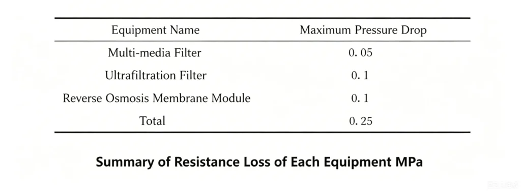
The total head loss caused by pipe friction and local resistance is calculated as:
Hf=6.761 mH_f = 6.761\,mHf=6.761m
Therefore, the selected pump head must exceed the total head loss. The chosen transfer pump model is 25GP-30 with a head of 30 m, confirming the correctness of the pump selection.
Related Articles
- Characteristics of Reverse Osmosis Membrane Fouling and Reverse Osmosis Membrane Cleaning Methods
- RO Plant in Dialysis: A Detailed Guide to the Reverse Osmosis System
- RO Plant for Dialysis: A Detailed Guide to the Pretreatment System
- How to Design a Dialysis Water Distribution Loop When a 40-machine Center Opens with Only 10 Machines
- Vertical vs Horizontal RO Membranes: Does Installation Orientation Matter?
- Optimizing Circulating Cooling Water Systems Using Reverse Osmosis Membrane Filtration Permeate
- Control and Prevention of Silica Fouling on RO Membranes
- RO Membrane Antiscalant Dosing: From Calculation Principles to Practical Application
- RO System Design: Series Staging or Concentrate Recirculation for Small RO Systems?
- Winter Maintenance Tips for Water Vending Machines
- Besides reverse osmosis membrane flux, what other key design parameters are easily overlooked but can significantly impact membrane life?
- NF Membrane VS RO Membrane VS Forward Osmosis Membrane
- How to Calculate Recovery Rate RO System?
- Relationship Between RO Membrane Element Pressure Limits and Recovery Rate in Water Reuse and Zero Liquid Discharge Applications
- How to Choose RO Membranes from China: 3 Key Factors to Consider