
Forms of Silica in Water
Silica in water can be divided into two main types: dissolved silica (also called reactive silica) and colloidal silica. What is often referred to as non-reactive silica is actually colloidal silica, or SiO₂, which cannot be detected by conventional testing methods. Ion exchange or other purification processes can only remove part of it. Colloidal silica is commonly found in water with high levels of soluble SiO₂ and low pH.
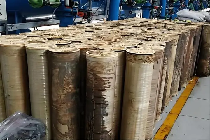
Colloidal silica doesn’t behave like ions and can be removed by physical filtration (such as ultrafiltration or cartridge filters) or by coagulation and sedimentation. Dissolved silica, on the other hand, is almost impossible to remove through physical filtration. When supersaturated, SiO₂ can spontaneously polymerize into insoluble colloidal or gelatinous silica, leading to membrane fouling.
Characteristics of SiO₂
The solubility of SiO₂ is significantly affected by temperature and pH. In reverse osmosis systems, the maximum SiO₂ concentration in the brine stream is about 120 mg/L. The higher the temperature and pH, the greater the silica solubility.
| pH | Solubility at 25°C (as SiO₂, mg/L) |
|---|---|
| 6–8 | 120 |
| 9 | 138 |
| 9.5 | 180 |
| 10 | 310 |
| 10.6 | 876 |
Based on these characteristics, there are three main strategies for controlling silica scaling in RO systems:
Reduce silica concentration in the brine
Increase the saturation solubility of silica in water
Use effective scale inhibitors to prevent silica scaling
Harmful Effects of Silica Scaling on RO Systems
Decreased permeate flow
When silica deposits on RO membrane surface, it forms a dense fouling layer that blocks water molecules from passing through the membrane pores, leading to a drop in permeate flow. This effect is gradual and may not be obvious at first. Pressure drop changes across stages are often not significant, which differs from other types of fouling.
Reduced salt rejection
Once silica scale forms, the charge characteristics and pore size distribution on the membrane surface change, making it easier for salts to pass through. As a result, the conductivity difference between the first and second RO stages becomes very pronounced. Moreover, the drop in salt rejection becomes even more noticeable after chemical cleaning, indicating that silica scaling may have caused some irreversible damage to the membrane.
Increased operating pressure
As silica accumulates on the membrane surface, the flow channels narrow, requiring higher pressure to maintain the same permeate flow. This also accelerates membrane aging.
Mechanical damage to membrane elements
Silica scale can scratch the membrane surface. This type of damage is irreversible — even after chemical cleaning, the original performance cannot be restored. For instance, salt rejection may drop from 97.06% to 92.90%.
More frequent cleaning
Control Measures for RO Silica Scaling
Reduce the RO system recovery rate
Increase feed water temperature
The maximum allowable feed water temperature for RO is 45°C. Raising the temperature helps dissolve silica but can also reduce the system’s salt rejection.
Adjust feed water pH
A high pH helps dissolve SiO₂, but it also increases the risk of CaCO₃ scaling.
Silica removal in pretreatment
Using a high-density sedimentation tank for hardness and silica removal — combining lime softening with MgO — can achieve over 60% SiO₂ removal, lowering SiO₂ concentration to below 10 mg/L.
Sodium aluminate is suitable for water with low hardness and high organic content. For high-hardness water, hardness must be removed first; otherwise, calcium and magnesium ions will compete with silica for adsorption, reducing silica removal efficiency.
Magnesium oxide works well for water with high hardness and low organic content. It generates more precipitate, which helps with silica adsorption and co-precipitation.
Iron, aluminum, and other metal ions are important catalysts for silica scaling. Therefore, these metals should be removed during pretreatment. It is recommended to use 1 micron filter cartridges to capture colloidal metal silicate particles.
Case example:
In one case, the brine had both high hardness and high silica content. Magnesium oxide was initially used for silica removal, but due to high COD in the feed water, the removal was poor, and silica in the product water remained at 50–100 mg/L. The process was then switched to sodium aluminate. In the first-stage high-density tank, NaOH, Na₂CO₃, PFS, and PAM were added to remove hardness and alkalinity. In the second-stage high-density tank, sodium aluminate was added to remove silica, with the sodium aluminate dosage at 2–3 times the silica concentration in the feed water.
Related Articles
- Characteristics of Reverse Osmosis Membrane Fouling and Reverse Osmosis Membrane Cleaning Methods
- RO Plant in Dialysis: A Detailed Guide to the Reverse Osmosis System
- RO Plant for Dialysis: A Detailed Guide to the Pretreatment System
- How to Design a Dialysis Water Distribution Loop When a 40-machine Center Opens with Only 10 Machines
- Vertical vs Horizontal RO Membranes: Does Installation Orientation Matter?
- Optimizing Circulating Cooling Water Systems Using Reverse Osmosis Membrane Filtration Permeate
- RO Membrane Antiscalant Dosing: From Calculation Principles to Practical Application
- RO System Design: Series Staging or Concentrate Recirculation for Small RO Systems?
- Winter Maintenance Tips for Water Vending Machines
- Small Reverse Osmosis Plant Process Details (0.5m3/Hour)
- Besides reverse osmosis membrane flux, what other key design parameters are easily overlooked but can significantly impact membrane life?
- NF Membrane VS RO Membrane VS Forward Osmosis Membrane
- How to Calculate Recovery Rate RO System?
- Relationship Between RO Membrane Element Pressure Limits and Recovery Rate in Water Reuse and Zero Liquid Discharge Applications
- How to Choose RO Membranes from China: 3 Key Factors to Consider