
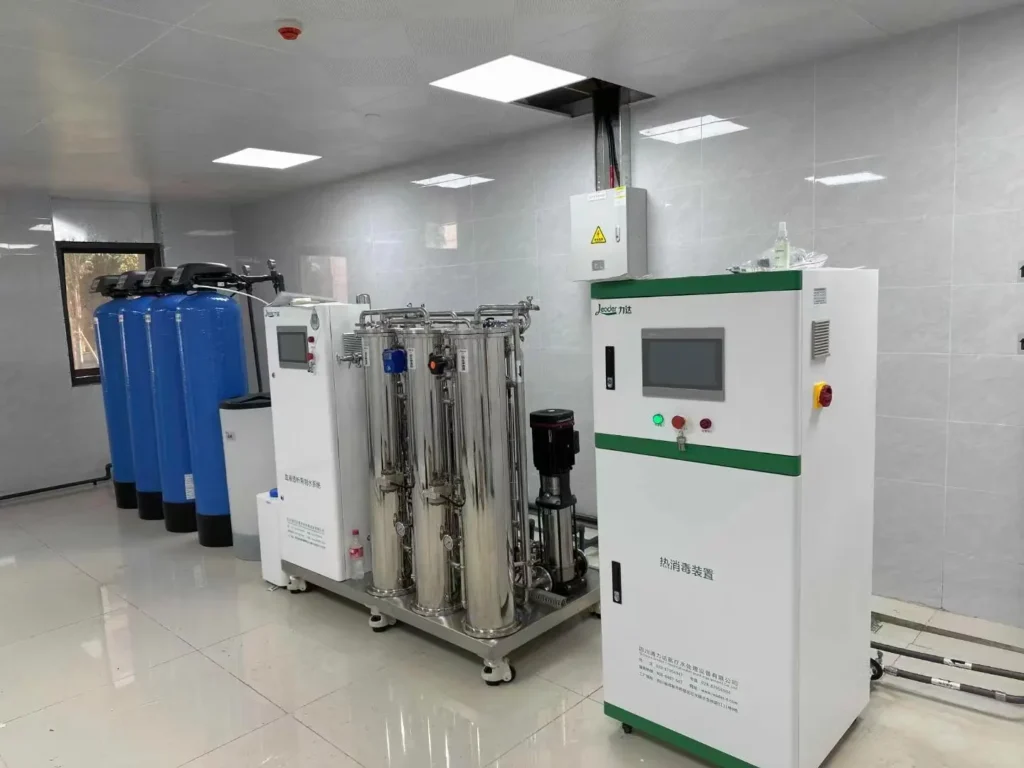
A new dialysis center is planned with 40 dialysis machines, but only around 10 machines will be put into operation initially because the patient load is still limited.
So how should the reverse osmosis system for dialysis be sized? More importantly, how should the water distribution loop be designed to minimize microbial growth when only part of the planned capacity is in use?
This is a critical design issue. If the distribution system is not designed correctly from the beginning, microbiological problems can appear soon after the center opens and may become difficult to control.
Why Can This Problem Occur?
Dialysis water is not ordinary tap water. Because of the high microbiological quality requirements for dialysis water, the treated water distribution system needs to be designed to minimize stagnation and maintain effective circulation.
1. Low Flow Velocity Creates Conditions for Biofilm Growth
Why does the water need to keep moving?
When water remains stagnant or the flow velocity is too low, conditions become more favorable for microbial growth and biofilm formation on the inner surfaces of the distribution piping.
Once a mature biofilm develops, routine disinfection can become much less effective because microorganisms can become embedded within the biofilm matrix. This is one reason why a dialysis center may obtain acceptable microbiological results immediately after disinfection but experience elevated counts again after a period of operation.
For dialysis water distribution systems, maintaining appropriate circulation and minimizing stagnant areas are therefore important design considerations.
A commonly referenced design value for the distal portion of a direct-feed system is approximately 1.5 ft/s (0.457 m/s) under peak-demand operating conditions. The actual design should always be verified against the applicable local requirements, current dialysis-water standards, and the specific system configuration.
However, there is an important problem when a system is designed for 40 dialysis machines but only 10 machines are initially operating.
If the distribution loop is sized for the future 40-machine capacity but the actual water demand is only a fraction of the final demand, the flow through the loop may be significantly lower than the design flow. Without an appropriate circulation strategy, low-flow areas can develop, particularly toward the distal sections of the loop.
2. The More Serious Problem: Dead Legs and Unused Branches
Low flow is not the only concern.
The 30 dialysis machines that are planned but not yet equipped with dialysis machines may leave unused branches or connection points in the distribution system.
If these branches are not properly designed and managed, they can become stagnant sections where water remains machineary for extended periods.
This is why dialysis water distribution systems should minimize dead legs, unused branches, and other areas where water can stagnate.
Flow velocity alone, however, is not a complete solution. Maintaining circulation can help reduce the risk of biofilm formation, but it does not replace an appropriate disinfection and microbiological monitoring program.
In other words:
Flow management is necessary, but it is not sufficient by itself.
For a dialysis center that opens in phases, both circulation and disinfection need to be properly managed.
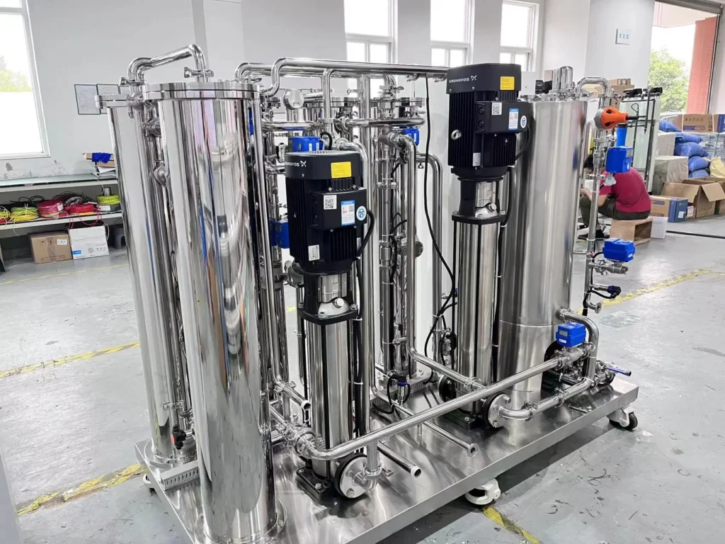
How Should a 40-machine Dialysis Center Be Designed for Phased Opening?
Strategy 1: Install the Distribution Loop for the Final Capacity, but Phase the Equipment Installation
This is generally the more practical engineering approach.
During the construction phase, the main supply and return distribution loop can be designed and installed according to the final 40-machine layout.
This avoids having to break walls, floors, or ceilings and modify the water distribution piping when additional dialysis machines are installed later.
The reverse osmosis system for dialysis and other water treatment equipment can be configured according to the actual initial demand, while reserving sufficient space and connection points for future expansion.
For example, if only 10 dialysis machines are initially operating, the initial RO production capacity can be determined based on the actual water demand, operating schedule, required flow, and future expansion plan.
As the center adds more dialysis machines, the water treatment capacity can then be expanded or upgraded accordingly.
The exact RO capacity should be calculated from the actual water consumption of the dialysis machines, peak demand, operating hours, distribution-loop requirements, redundancy requirements, and applicable project specifications rather than simply multiplying the number of machines by a fixed flow rate.
Strategy 2: Eliminate Dead Legs and Properly Close Unused Connection Points
This is one of the details that is easy to overlook.
The 30 connection points that are not initially connected to dialysis machines should not simply be left open or blocked with improvised materials.
Unused branches should be designed and terminated in a way that minimizes stagnant water.
Where appropriate, dedicated sanitary caps, valves, or other piping components compatible with the distribution system should be used according to the system design.
If a temporary branch is designed to be flushed or disinfected during commissioning and maintenance, the piping arrangement should allow the disinfectant and flushing water to reach the relevant section effectively.
The key principle is simple:
Do not create an isolated section of piping that cannot be properly flushed, disinfected, and maintained.
Strategy 3: Use a Recirculation Loop to Maintain Appropriate Flow
When only 10 dialysis machines are operating, their water demand may not be sufficient to maintain the desired circulation conditions throughout a distribution loop designed for 40 machines.
A properly designed recirculation system can address this issue.
The return line brings treated water back toward the RO or designated treatment point, creating continuous circulation through the distribution loop.
Depending on the system configuration, a circulation pump, balancing arrangement, or bypass/recirculation line can be incorporated to maintain appropriate flow through the loop even when only part of the dialysis center is operating.
The objective is to avoid low-flow sections and minimize stagnant areas.
This design should be considered during the initial engineering stage. It is much more difficult and expensive to modify the distribution loop after the dialysis center has been completed.
Strategy 4: Disinfection Must Cover the Entire Distribution System
Another common mistake is to assume that unused sections do not need to be disinfected because the corresponding dialysis machines have not yet been installed.
This is not a good approach.
The disinfection strategy should cover the complete water distribution system, including sections serving temporarily unused machines, provided that those sections are part of the active distribution network.
The applicable disinfection method, frequency, contact time, flushing procedure, and verification requirements should be determined according to the equipment manufacturer’s instructions, project specifications, applicable standards, and microbiological monitoring results.
For a phased-opening dialysis center, a partially occupied facility can actually present additional water-quality management challenges because the distribution network may be operating below its final design demand.
Therefore, disinfection should not simply be reduced because fewer dialysis machines are operating.
Strategy 5: Increase Water Quality Monitoring During the Initial Operating Period
The initial operating period is especially important for a newly commissioned dialysis water treatment and distribution system.
Instead of waiting until microbiological results exceed an action level, establish a monitoring program that can identify unfavorable trends early.
Depending on the applicable local requirements and the center’s water-quality management program, monitoring may include:
Microbiological testing at representative points
Sampling from both the beginning and distal sections of the distribution loop
Regular monitoring of operating conditions
Trend analysis of microbiological results
Verification after disinfection
Investigation of any abnormal increase in microbial counts
For example, during the initial months of operation, the dialysis center may consider a more frequent sampling schedule than the routine long-term schedule, based on its risk assessment and applicable requirements.
The goal is not simply to react when water quality fails.
The goal is to identify changes early and correct the underlying cause before a larger microbiological problem develops.
Key Design Principles for a Phased Dialysis Center
When a dialysis center is designed for 40 machines but initially operates only 10 machines, the water treatment and distribution system should be designed around the final capacity while accommodating the initial operating condition.
The key principles are:
Plan the main distribution loop for the final number of dialysis machines.
Avoid dead legs and unnecessary unused branches.
Provide appropriate recirculation to maintain effective circulation when demand is low.
Make sure the entire active distribution network can be flushed and disinfected.
Do not reduce disinfection simply because fewer dialysis machines are operating.
Increase monitoring and trend analysis during the initial operating period.
Design the reverse osmosis system for dialysis based on actual water demand, peak demand, redundancy, and future expansion requirements.
A well-designed dialysis water system should not only meet the water-quality requirements at the RO outlet. The treatment system, distribution loop, disinfection strategy, and monitoring program must work together to maintain water quality all the way to the dialysis machines.
For a phased dialysis center, designing for future expansion while maintaining proper circulation at the initial operating capacity is one of the most important considerations in the overall reverse osmosis system for dialysis design.
Related Articles
- Characteristics of Reverse Osmosis Membrane Fouling and Reverse Osmosis Membrane Cleaning Methods
- RO Plant in Dialysis: A Detailed Guide to the Reverse Osmosis System
- RO Plant for Dialysis: A Detailed Guide to the Pretreatment System
- Vertical vs Horizontal RO Membranes: Does Installation Orientation Matter?
- Optimizing Circulating Cooling Water Systems Using Reverse Osmosis Membrane Filtration Permeate
- Control and Prevention of Silica Fouling on RO Membranes
- RO Membrane Antiscalant Dosing: From Calculation Principles to Practical Application
- RO System Design: Series Staging or Concentrate Recirculation for Small RO Systems?
- Winter Maintenance Tips for Water Vending Machines
- Small Reverse Osmosis Plant Process Details (0.5m3/Hour)
- Besides reverse osmosis membrane flux, what other key design parameters are easily overlooked but can significantly impact membrane life?
- NF Membrane VS RO Membrane VS Forward Osmosis Membrane
- How to Calculate Recovery Rate RO System?
- Relationship Between RO Membrane Element Pressure Limits and Recovery Rate in Water Reuse and Zero Liquid Discharge Applications
- How to Choose RO Membranes from China: 3 Key Factors to Consider