
Article Overview
Selecting the right high pressure RO water pump is critical for achieving reliable performance, optimal water production, and long-term energy efficiency in reverse osmosis systems. An improperly sized pump can increase operating costs, reduce membrane performance, and shorten equipment life.
This guide covers the key engineering principles behind high pressure RO pump selection, including pump operating fundamentals, sizing calculations, performance curve interpretation, energy-saving technologies, and a real-world design example.
In This Article
Why the high pressure pump is the most critical component in an RO system
How reverse osmosis pumps generate the pressure required for membrane separation
Key selection parameters including flow rate, pressure, efficiency, NPSH, and motor power
Comparison of multistage centrifugal pumps, plunger pumps, and other common RO pump types
Step-by-step methods for calculating pump flow rate and operating pressure
How to read and interpret pump performance curves
Energy-saving strategies including VFD control and energy recovery devices (ERDs)
A practical engineering example of high pressure RO water pump sizing
A complete pump selection checklist for RO system designers and engineers
By the end of this guide, you will have a clear understanding of how to select a high pressure RO water pump that balances performance, reliability, and operating cost for your specific application.
Operating Principles and Key Design Parameters
Why the High Pressure Pump Matters in an RO System
In any reverse osmosis (RO) system, the high pressure pump is often considered the heart of the entire process. Its primary function is to provide sufficient pressure to overcome the osmotic pressure of the feed water and drive water molecules through the semi-permeable membrane.
The performance of the high pressure RO water pump directly affects system productivity, permeate quality, recovery rate, and long-term operating costs. An undersized pump may result in insufficient membrane flux, while an oversized pump can increase energy consumption and unnecessary capital investment.
In a typical industrial RO plant, the high pressure pump can account for approximately 35%–50% of the total operating energy cost. Selecting the right pump is therefore one of the most important engineering decisions during system design.
This guide explains the operating principles, pump types, sizing calculations, performance analysis, and practical selection considerations for high pressure RO pumps.
Key Parameters for Pump Selection
Several critical parameters must be evaluated when selecting a high pressure RO water pump.
Flow Rate (Q)
Flow rate represents the volume of liquid delivered by the pump per unit time and is usually expressed in m³/h or L/min.
The design flow should be determined based on the required permeate production, system recovery rate, and a reasonable design margin. In most applications, engineers select a pump capacity approximately 10–20% higher than the calculated design flow.
Pressure or Head (H)
Pump discharge pressure must be sufficient to overcome osmotic pressure and all hydraulic losses within the RO system.
The required pressure can be estimated as:
Pump Pressure ≥ Osmotic Pressure + Net Driving Pressure + System Pressure Loss + Safety Margin
Pump Efficiency (η)
Pump efficiency is the ratio between hydraulic output power and shaft input power.
A high-efficiency pump significantly reduces electricity consumption over the system’s operating life. Modern industrial multistage centrifugal pumps typically achieve efficiencies between 70% and 82%.
Net Positive Suction Head Required (NPSHr)
NPSHr indicates the minimum inlet pressure required to prevent cavitation inside the pump.
The available NPSH (NPSHa) should always exceed the required NPSH by at least 0.5–1.0 meters to ensure reliable operation.
Shaft Power (Pa)
The shaft power required by the pump can be estimated using:
Pa=ρ×g×Q×H3600×ηPa=\frac{\rho \times g \times Q \times H}{3600 \times \eta}Pa=3600×ηρ×g×Q×H
where:
- Pa = shaft power (kW)
- ρ = fluid density (kg/m³)
- g = gravitational acceleration (9.81 m/s²)
- Q = flow rate (m³/h)
- H = pump head (m)
- η = pump efficiency
Accurate shaft power calculation is essential for selecting the correct motor size and avoiding overloading during operation.
Common Types of High Pressure RO Pumps
Several types of high pressure pumps are commonly used in reverse osmosis systems today. Each pump design offers unique advantages and is suited to specific operating conditions.
| Pump Type | Pressure Range | Key Advantages | Typical Applications | Common Brands |
|---|---|---|---|---|
| Multistage Centrifugal Pump | 1.0–8.0 MPa | High flow capacity, smooth operation, easy maintenance, cost-effective | Medium and large RO systems (>10 m³/h) | Grundfos, CNP |
| Plunger/Piston Pump | 3.0–80 MPa | Extremely high pressure capability, high efficiency (>85%), precise flow control | Seawater desalination, low-flow high-pressure systems | Danfoss, CAT Pumps |
| Diaphragm Pump | 0.5–7.0 MPa | Leak-free operation, self-priming capability, dry-run tolerance | Small RO units, laboratory systems | ARO, Wilden |
| Energy Recovery Integrated Pump | 4.0–7.0 MPa | Significant energy savings (40–60%), integrated pressure recovery | Large seawater desalination plants | Flowserve, KSB |
Table 1. Comparison of Common High Pressure RO Pump Types
Multistage Centrifugal Pumps – The Preferred Choice for Most Industrial RO Systems
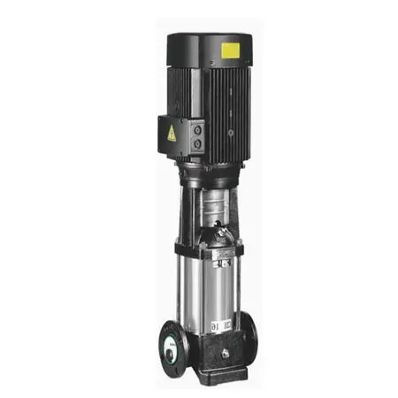
Multistage centrifugal pumps are by far the most widely used type of high pressure RO water pump in industrial reverse osmosis applications.
By arranging multiple impellers in series, these pumps gradually increase pressure while maintaining stable flow and high operating efficiency over a wide range of conditions.
Their popularity is largely due to several advantages:
- Simple and proven design
- Reliable long-term operation
- Low maintenance requirements
- Competitive purchase cost
- Wide availability of spare parts
For brackish water RO systems and ultrapure water production systems using municipal water supplies, multistage centrifugal pumps are typically the most economical and practical solution.
Selection Recommendations
When selecting a multistage centrifugal pump for an RO system, engineers should consider the following:
- Choose stainless steel wetted components, preferably SS304 or SS316, to ensure adequate corrosion resistance.
- Verify that the design operating point falls within the pump’s high-efficiency zone.
- Ideally, the duty point should remain within 80%–110% of the Best Efficiency Point (BEP).
- For systems with varying production demand, a Variable Frequency Drive (VFD) is highly recommended to improve energy efficiency and provide flexible flow control.
Plunger Pumps – Ideal for Seawater Desalination and High-Pressure Applications
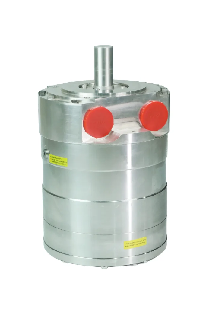
Plunger pumps belong to the positive displacement pump family. Fluid is transported through the reciprocating motion of a plunger inside a cylinder.
Unlike centrifugal pumps, plunger pumps can generate extremely high discharge pressures even at relatively low flow rates.
Their major advantages include:
- Pressure capability far beyond that of centrifugal pumps
- Volumetric efficiency often exceeding 90%
- Accurate and stable flow delivery
- Excellent energy utilization under high-pressure conditions
For seawater reverse osmosis (SWRO) systems, particularly small and medium-sized desalination units, plunger pumps are widely used because of their outstanding pressure performance and operating efficiency.
They are also commonly employed in specialized membrane applications such as:
- Disc Tube Reverse Osmosis (DTRO)
- Spiral Tube Reverse Osmosis (STRO)
- Landfill leachate treatment systems
- High-salinity wastewater treatment
Design Considerations
While plunger pumps offer excellent pressure capabilities, several factors should be considered:
- Feed water quality must be carefully controlled, as suspended solids can accelerate seal wear.
- Flow pulsation is inherent to reciprocating pump designs. Installing a pulsation dampener is recommended to protect downstream membrane elements and piping.
- Routine maintenance, including replacement of seals and plungers, is necessary to ensure reliable operation.
High Pressure RO Pump Sizing Calculations
Proper sizing is one of the most important steps when selecting a high pressure RO water pump. Undersized pumps may fail to provide sufficient membrane pressure, while oversized pumps increase both capital cost and operating expenses.
The sizing process generally involves determining three key parameters:
- Required flow rate
- Required discharge pressure
- Required motor power
Determining Pump Flow Rate
The design flow rate should be calculated based on the required permeate production and system recovery rate.
The basic sizing formula is:
Qpump=QpermeateRecovery×KQ_{pump}= \frac{Q_{permeate}}{Recovery} \times KQpump=RecoveryQpermeate×K
Where:
- QpumpQ_{pump}Qpump = required pump flow rate
- QpermeateQ_{permeate}Qpermeate = desired permeate production rate
- Recovery = system recovery ratio
- KKK = safety factor (typically 1.1–1.2)
The safety factor compensates for:
- Membrane fouling over time
- Seasonal temperature variations
- Future production fluctuations
Example Calculation
Assume an RO system is designed to produce:
- Permeate flow: 20 m³/h
- Recovery rate: 75%
- Safety factor: 1.15
The required pump flow becomes:
20÷0.75×1.1520 \div 0.75 \times 1.1520÷0.75×1.15 ≈30.7 m3/h\approx 30.7\;m^3/h≈30.7m3/h
Therefore, a pump rated at approximately 31 m³/h should be selected.
Determining Required Pump Pressure
Calculating discharge pressure is the most critical step in RO pump selection.
The required pressure consists of several components:
| Pressure Component | Description | Typical Range |
|---|---|---|
| Osmotic Pressure (π) | Determined by feed water salinity and concentration factor | Municipal water: 0.02–0.05 MPaBrackish water: 0.1–0.8 MPaSeawater: 2.4–2.7 MPa |
| Net Driving Pressure (NDP) | Effective pressure required for membrane permeation | Typically 0.5–1.2 MPa |
| System Pressure Loss (ΔP) | Pressure losses through piping, valves, and membrane vessels | Approximately 0.04–0.07 MPa per membrane element |
| Concentrate Back Pressure | Pressure maintained before concentrate discharge | Usually 0.1–0.3 MPa |
| Safety Margin | Allowance for membrane fouling and operating fluctuations | 10–20% of total pressure |
Table 2. Components of Required RO Pump Pressure
The total required discharge pressure can be estimated as:
Ppump=π+NDP+ΔP+Pback+Safety MarginP_{pump} = \pi + NDP + \Delta P + P_{back} + Safety\ MarginPpump=π+NDP+ΔP+Pback+Safety Margin
Engineers should always verify the calculation under the most demanding operating conditions, such as low water temperature or maximum feed salinity.
Motor Power Calculation
After determining the required flow and pressure, the next step is to calculate the pump shaft power and select an appropriately sized motor.
The commonly used formula is:
Pa(kW)=Q(m3/h)×H(m)×ρ(kg/m3)367×ηpumpPa(kW) = \frac{Q(m^3/h)\times H(m)\times \rho(kg/m^3)} {367\times \eta_{pump}}Pa(kW)=367×ηpumpQ(m3/h)×H(m)×ρ(kg/m3)
Where:
- Pa = pump shaft power (kW)
- Q = flow rate (m³/h)
- H = pump head (m)
- ρ = fluid density (kg/m³)
- η = pump efficiency
Motor Selection Guidelines
When selecting the motor:
- Motor rated power should typically be 10–25% higher than the calculated shaft power.
- Always select the next standard motor size above the calculated requirement.
- If a Variable Frequency Drive (VFD) will be used, the VFD capacity should be slightly larger than the motor rating.
- For installations located at elevations above 1,000 meters, additional power margin may be necessary due to reduced cooling performance caused by lower air density.
Proper motor sizing improves reliability and prevents overload conditions during peak operating periods.
Understanding Pump Performance Curves and Operating Data
Every high pressure RO water pump is supplied with a set of performance curves by the manufacturer. These curves are essential tools for engineers when evaluating pump suitability and verifying operating conditions.
The most commonly used pump performance curves include:
- Head vs. Flow Curve (H-Q)
- Efficiency vs. Flow Curve (η-Q)
- NPSHr vs. Flow Curve
- Power vs. Flow Curve (Pa-Q)
The following table illustrates typical performance data for a multistage centrifugal pump operating at 2900 rpm.
Typical Multistage High Pressure Pump Performance Data
| Flow Q (m³/h) | Head H (m) | Efficiency η (%) | NPSHr (m) | Shaft Power Pa (kW) | Operating Condition | Deviation from BEP | Engineering Remarks |
|---|---|---|---|---|---|---|---|
| 20 | 218 | 63 | 2.8 | 18.9 | Partial Load | -35% | Low efficiency, avoid continuous operation |
| 24 | 215 | 70 | 3.0 | 21.0 | Partial Load | -25% | Acceptable for short-term operation |
| 28 | 211 | 76 | 3.3 | 23.5 | Near Efficient Zone | -12% | Usable but not optimal |
| 32 | 206 | 80 | 3.7 | 25.8 | Edge of Efficient Zone | -5% | Recommended lower operating limit |
| 36 | 199 | 82.5 | 4.2 | 27.8 | Best Efficiency Point (BEP) | 0% | Optimum operating condition |
| 40 | 190 | 80.5 | 4.7 | 29.6 | High Efficiency Zone | +7% | Recommended upper operating limit |
| 44 | 179 | 77 | 5.2 | 31.2 | High Flow Region | +18% | Efficiency decline becomes noticeable |
| 48 | 165 | 71 | 5.6 | 33.8 | Near Run-Out Condition | +30% | Avoid continuous operation; cavitation risk increases |
Table 3. Typical Performance Data for a Multistage High Pressure RO Pump
Interpreting the Key Performance Curves
Head vs. Flow Curve (H-Q)
The H-Q curve shows the relationship between pump flow rate and developed head.
For centrifugal pumps, head decreases as flow increases. This behavior is normal and must be considered during system design.
When selecting a pump, the system duty point should ideally fall directly on the curve or slightly to the left of the design point to provide a reasonable operating margin.
Operating too far to the right may result in excessive flow, reduced pressure, and unstable performance.
Efficiency vs. Flow Curve (η-Q)
The efficiency curve indicates how efficiently the pump converts mechanical energy into hydraulic energy at different flow rates.
The highest point on the curve is known as the Best Efficiency Point (BEP).
For reliable and economical operation, the actual operating point should remain within approximately 80%–110% of the BEP flow rate.
Running significantly away from the BEP can result in:
- Increased energy consumption
- Higher vibration levels
- Premature bearing wear
- Mechanical seal failures
- Reduced pump life
For most industrial RO systems, selecting a pump whose normal operating condition falls close to the BEP is considered best practice.
NPSHr vs. Flow Curve
The Net Positive Suction Head Required (NPSHr) curve indicates the minimum inlet pressure needed to prevent cavitation.
Cavitation occurs when the local pressure inside the pump falls below the liquid vapor pressure, causing vapor bubbles to form and collapse violently.
The consequences of cavitation include:
- Noise and vibration
- Impeller erosion
- Reduced pump performance
- Shortened equipment life
A lower NPSHr value generally indicates better resistance to cavitation and greater flexibility in system design.
Engineers should always verify that:
NPSHa > NPSHr + Safety Margin
A safety margin of at least 0.5–1.0 meters is generally recommended.
Power vs. Flow Curve (Pa-Q)
The power curve shows how shaft power changes with flow rate.
For centrifugal pumps, power consumption typically increases as flow increases.
This characteristic is important when selecting motors and protection devices.
A motor that is undersized may overload when the pump operates near maximum flow conditions.
For this reason, motor selection should always consider the maximum expected operating point rather than only the design duty point.
Energy-Saving Technologies for High Pressure RO Pumps
Because the high pressure RO water pump is usually the largest energy consumer in a reverse osmosis plant, improving pump efficiency can significantly reduce operating costs.
Modern RO systems often incorporate a combination of the following energy-saving technologies.
Variable Frequency Drive (VFD) Control
A Variable Frequency Drive (VFD) adjusts motor speed by changing the frequency of the electrical power supplied to the motor.
Unlike conventional throttling control methods, VFD systems regulate flow by directly adjusting pump speed, which greatly reduces energy losses.
VFD technology is particularly beneficial for systems where:
- Feed water conditions fluctuate
- Product water demand varies throughout the day
- Seasonal operating changes occur
- Multiple operating modes are required
Field experience has shown that properly implemented VFD control can reduce pump energy consumption by approximately 15%–30%.
In multi-stage RO systems, advanced VFD control can also improve membrane flux distribution and reduce membrane fouling rates.
Energy Recovery Devices (ERDs)
In high-salinity RO systems, particularly seawater desalination plants, the concentrate stream still contains a substantial amount of hydraulic energy.
Instead of wasting this energy, Energy Recovery Devices (ERDs) transfer it back to the incoming feed stream.
This significantly reduces the load on the high pressure pump.
The most common energy recovery technologies include:
Pelton Turbine Systems
Pelton turbines recover pressure energy from the concentrate stream and convert it into mechanical energy.
Although reliable, they are less efficient than modern alternatives.
Pressure Exchanger (PX) Technology
Pressure exchangers directly transfer pressure from the concentrate stream to the incoming feed water.
This technology is currently considered the industry standard for large seawater desalination facilities due to its exceptionally high efficiency.
Integrated Energy Recovery Pumps
A newer development combines pumping and energy recovery functions into a single integrated unit.
These systems offer:
- Compact footprint
- Reduced piping complexity
- Simplified installation
- Improved overall efficiency
In large seawater RO plants, effective ERD implementation can reduce specific energy consumption from approximately 4.5–6.0 kWh/m³ to as low as 2.5–3.5 kWh/m³.
Overall energy savings of 40%–60% are common.
Lorem ipsum dolor sit amet, consectetur adipiscing elit. Ut elit tellus, luctus nec ullamcorper mattis, pulvinar dapibus leo.
Additional Energy-Saving Measures
Use High-Efficiency Motors
Modern IE3 and IE4 premium-efficiency motors can reduce electrical losses compared to standard motors.
Permanent Magnet Synchronous Motors (PMSMs) can provide even higher efficiency in certain applications.
Typical energy savings range from 3% to 8%.
Optimize Piping Design
Poor piping design often creates unnecessary pressure losses.
Engineers should:
- Use properly sized pipe diameters
- Minimize unnecessary bends and fittings
- Select low-resistance valves
- Reduce flow restrictions wherever possible
Lower system pressure losses directly reduce pump energy requirements.
Maintain Appropriate Feed Water Temperature
As temperature increases, water viscosity decreases and membrane permeability improves.
In many RO systems, a 1°C increase in feed water temperature can reduce required operating pressure by approximately 3%.
However, membrane temperature limitations must always be respected.
Perform Regular Membrane Cleaning
Membrane fouling increases differential pressure and reduces permeate flux.
As fouling worsens, the high pressure pump must work harder to maintain production rates.
Routine membrane cleaning helps restore system performance and indirectly reduces pump energy consumption.
Practical Pump Selection Example
High Pressure RO Pump Selection for an Ultrapure Water System
Project Background
A semiconductor manufacturing facility in Eastern China requires an ultrapure water production system using municipal water as the feed source. The system utilizes a two-pass reverse osmosis process, with the following design parameters for the first-pass RO system:
Design Conditions
- Permeate capacity: 25 m³/h
- System recovery rate: 75%
- Feed water TDS: approximately 250 mg/L
- Membrane array configuration: 6:3 staging arrangement
- Membrane size: 8-inch elements
- Design water temperature: 15–25°C
The objective is to select a suitable high pressure RO water pump that meets both performance and energy-efficiency requirements.
Step 1: Calculate Required Pump Flow Rate
Using the sizing equation introduced earlier:
Qpump=QpermeateRecovery×KQ_{pump}=\frac{Q_{permeate}}{Recovery}\times KQpump=RecoveryQpermeate×K
Assuming a design safety factor of 1.15:
Qpump=25÷0.75×1.15Q_{pump}=25\div0.75\times1.15Qpump=25÷0.75×1.15 Qpump≈38.3 m3/hQ_{pump}\approx38.3\;m^3/hQpump≈38.3m3/h
For engineering simplicity and future operating flexibility, the design flow rate is rounded up to:
Selected Pump Flow Rate = 40 m³/h
Step 2: Estimate Osmotic Pressure
Since the feed water is municipal water with relatively low salinity:
- Feed-end osmotic pressure ≈ 0.023 MPa
- Concentrate-end osmotic pressure (approximately 4× concentration factor) ≈ 0.08 MPa
The maximum osmotic pressure used for design purposes is therefore:
π ≈ 0.08 MPa
Step 3: Determine System Pressure Losses
Pressure losses originate from:
- Membrane elements
- Pressure vessels
- Interconnecting piping
- Valves and fittings
For this system:
- Total membrane elements: 9
- Estimated membrane and piping pressure loss: approximately 0.55 MPa
Therefore:
ΔP ≈ 0.55 MPa
Step 4: Determine Required Net Driving Pressure
Based on membrane manufacturer recommendations and considering low-temperature operation:
Net Driving Pressure (NDP) = 0.9 MPa
This value provides sufficient driving force for stable permeate production under the most demanding operating conditions.
Step 5: Calculate Total Pressure Requirement
The total pump discharge pressure is estimated as:
Ptotal=π+NDP+ΔP+Safety MarginP_{total} = \pi + NDP + \Delta P + Safety\ MarginPtotal=π+NDP+ΔP+Safety Margin
Substituting the calculated values:
0.08+0.90+0.55+0.200.08+0.90+0.55+0.200.08+0.90+0.55+0.20 =1.73 MPa= 1.73\;MPa=1.73MPa
To provide additional operational flexibility:
Selected Design Pressure = 1.8 MPa
Step 6: Calculate Pump Shaft Power
The required shaft power can be estimated using:
Pa=Q×H×ρ367×ηPa= \frac{Q\times H\times \rho} {367\times \eta}Pa=367×ηQ×H×ρ
Assuming:
- Flow rate = 40 m³/h
- Head = 183 m
- Pump efficiency = 78%
The calculated shaft power is:
Pa=40×183367×0.78Pa = \frac{40\times183} {367\times0.78}Pa=367×0.7840×183 Pa≈25.6 kWPa\approx25.6\;kWPa≈25.6kW
To ensure adequate motor capacity:
Selected Motor Size = 30 kW
Final Pump Selection
Based on the above calculations, a suitable selection would be:
Pump Specifications
- Pump Type: Horizontal multistage centrifugal pump
- Rated Flow: 40 m³/h
- Rated Pressure: 1.8 MPa
- Motor Power: 30 kW
- Motor Efficiency Class: IE3 Premium Efficiency
- Speed Control: Variable Frequency Drive (VFD)
- Wetted Materials: SS316 stainless steel
- Mechanical Seal: SiC/SiC double mechanical seal
A pump comparable to the Grundfos CR series or an equivalent industrial-grade model would be suitable for this application.
Expected Benefits
This solution provides:
- Reliable operation under varying feed conditions
- High energy efficiency
- Reduced maintenance requirements
- Long membrane service life
- Reasonable capital investment
Based on an annual operating time of 8,000 hours and an electricity cost of USD 0.11/kWh (or approximately RMB 0.8/kWh), the estimated annual electricity cost for the pump is approximately:
USD 16,000–18,000 per year
depending on actual operating conditions.
Final Selection Checklist and Summary
Selecting the right high pressure RO water pump requires balancing hydraulic performance, reliability, corrosion resistance, and long-term operating costs.
The following checklist can help engineers evaluate pump suitability during project design and procurement.
High Pressure RO Pump Selection Checklist
| Item | Evaluation Point | Key Considerations |
|---|---|---|
| 1 | Verify Basic Design Data | Permeate flow, recovery rate, feed water quality, temperature, and operating conditions |
| 2 | Calculate Required Flow and Pressure | Include a reasonable safety margin and evaluate worst-case conditions |
| 3 | Select the Appropriate Pump Type | Match centrifugal, plunger, or other pump types to the application requirements |
| 4 | Verify NPSH Conditions | Ensure NPSHa exceeds NPSHr by at least 0.5 m |
| 5 | Confirm Material Compatibility | SS304/SS316 for freshwater; duplex stainless steel or special alloys for seawater |
| 6 | Calculate Shaft Power and Select Motor | Motor rating should exceed calculated shaft power by 10–25% |
| 7 | Evaluate VFD Requirements | Strongly recommended for variable-load applications |
| 8 | Assess Energy Recovery Opportunities | Essential for seawater desalination and other high-pressure systems |
| 9 | Review Supplier Support Capabilities | Availability of spare parts, local service, and technical support |
| 10 | Prepare a Complete Technical Specification | Include performance guarantees, material certifications, and acceptance criteria |
Table 4. High Pressure RO Water Pump Selection Checklist
Conclusion
The high pressure RO water pump is one of the most critical components in any reverse osmosis system. Proper pump selection not only ensures stable system performance but also has a significant impact on energy consumption, operating costs, and equipment reliability.
A successful pump selection process should always begin with accurate process data and include careful evaluation of:
- Required flow rate
- Operating pressure
- Pump efficiency
- NPSH requirements
- Material compatibility
- Motor sizing
- Energy-saving opportunities
For most industrial RO applications, multistage centrifugal pumps remain the preferred solution due to their reliability, efficiency, and cost-effectiveness. In seawater desalination and ultra-high-pressure applications, plunger pumps and advanced energy recovery technologies often provide the best overall performance.
Because every RO project has unique operating conditions, engineers are encouraged to work closely with pump manufacturers and system suppliers to compare technical proposals, evaluate lifecycle costs, and identify the most suitable solution.
A well-selected high pressure RO water pump can deliver years of reliable service while significantly reducing the total cost of water production.