

RO pressure vessels are essential components in reverse osmosis systems, designed to house membrane elements under high pressure.
They play a critical role in ensuring system efficiency, safety, and durability.
In this guide, we’ll cover different types, materials, and how to choose the right RO pressure vessel for your application.
What are RO Pressure Vessels?
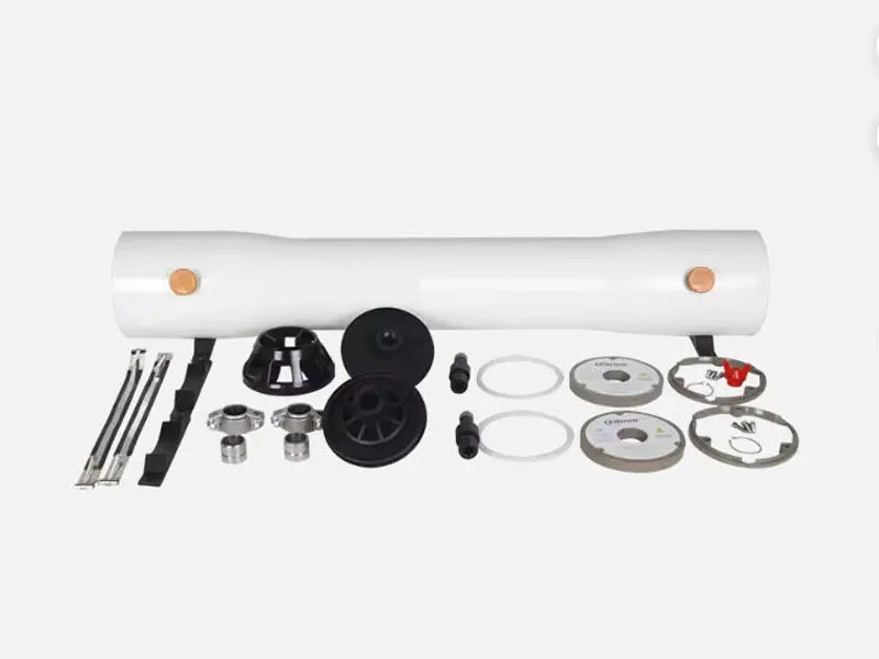
RO Pressure Vessels are core pressure-bearing components in reverse osmosis (RO) water treatment systems. These RO Pressure Vessels are primarily designed to house RO membrane elements and withstand high operating pressure, ensuring efficient water separation and permeate production across the membrane surface.
Functional Role:
As the “protective chamber” and “pressure container” for RO membranes, RO Pressure Vessels do not directly perform filtration. However, they are essential for maintaining stable membrane operation, ensuring reliable sealing, and providing the necessary pressure resistance for the entire system.
Structure:
Typical RO Pressure Vessels consist of a cylindrical shell, end caps, locking mechanisms, and sealing systems (such as O-rings and V+X rings). Some RO Pressure Vessels are designed with modular structures to facilitate easier maintenance and replacement.
Material Types:
FRP (Fiberglass Reinforced Plastic): Commonly used in RO Pressure Vessels due to its excellent corrosion resistance and electrical insulation, making it ideal for seawater desalination and industrial applications.
Stainless Steel (304/316L): Used in high-end RO Pressure Vessels, offering superior mechanical strength and pressure resistance, suitable for food, beverage, and pharmaceutical industries.
Engineering Plastics (e.g., PP): Applied in small-scale RO Pressure Vessels for household water purifiers, providing a cost-effective solution with relatively lower pressure resistance and lifespan.
In summary, RO Pressure Vessels are critical pressure-bearing and sealing components that ensure the long-term stable operation of RO membranes under high-pressure and corrosive conditions. The quality of RO Pressure Vessels directly affects system safety, desalination efficiency, and overall service life.
How do RO Pressure Vessels Work?
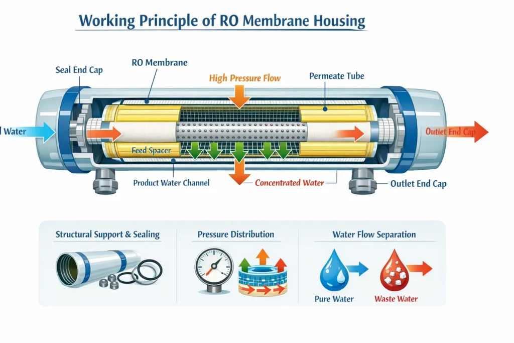
RO Pressure Vessels do not directly participate in the reverse osmosis separation process. Instead, they serve as the supporting and enclosing structure for RO membrane elements. The working principle of RO Pressure Vessels is closely related to the overall operation of the RO system, as explained below:
1. Structural Support and Sealing Function
RO Pressure Vessels are typically made of materials such as FRP (fiberglass reinforced plastic), stainless steel, or engineering plastics. Inside the vessel, they provide mechanical support for membrane elements (such as spiral wound RO membranes), ensuring the membranes maintain a stable shape under high pressure and preventing deformation or damage.
At the same time, RO Pressure Vessels achieve reliable sealing through components such as O-rings, end caps, and sealing systems, allowing feed water, permeate, and concentrate to flow within their respective channels without leakage. This ensures stable system pressure and safe operation.
2. Pressure Transmission and Distribution
After the feed water is pressurized by a high-pressure pump, the pressure is transferred through the RO Pressure Vessels to the surface of the membrane elements. The design of RO Pressure Vessels ensures that pressure is evenly distributed across the membrane surface, preventing localized high or low pressure that could negatively affect membrane performance and lifespan.
For example, in spiral wound configurations, RO Pressure Vessels work together with the central tube and spacer structure to ensure uniform pressure application, allowing water molecules to pass evenly through the membrane under pressure.
3. Water Flow Guidance and Separation
Inside RO Pressure Vessels, there are feed spacers, permeate channels, and concentrate flow paths. Feed water enters the membrane element through the spacer channels, and under pressure, water molecules pass through the membrane into the permeate channel, eventually collecting in the central tube as purified water.
Meanwhile, the concentrated water containing salts and impurities is discharged through the concentrate flow channel, achieving effective separation.
In summary, RO Pressure Vessels act as the “shell” and “framework” of the RO system. Through structural support, sealing, pressure transmission, and flow guidance, they create a stable operating environment for membrane elements, ensuring the reverse osmosis process runs efficiently and reliably.
Types of RO Pressure Vessels
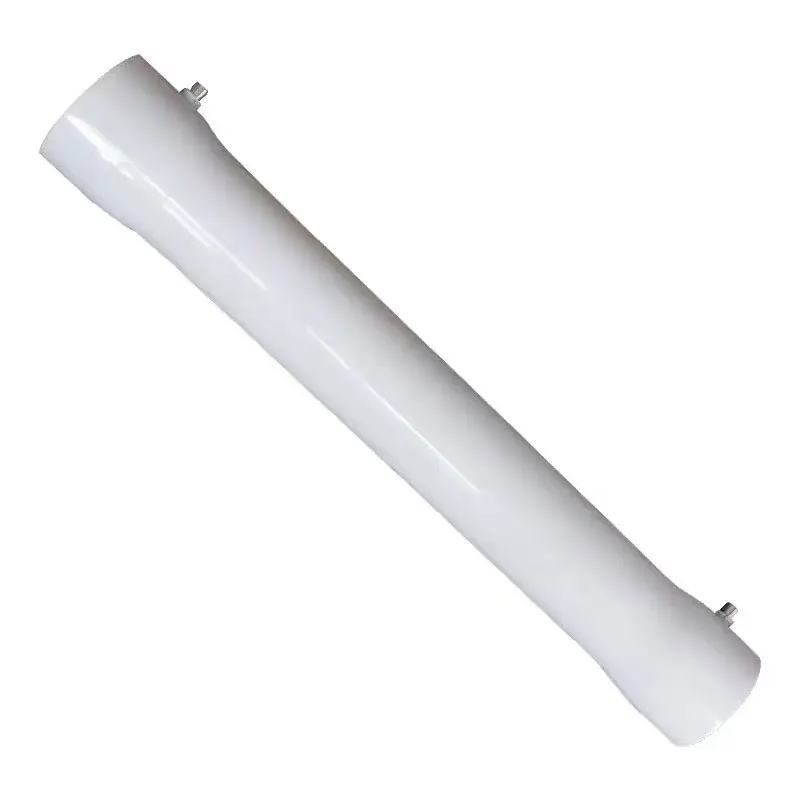

By Structure
| Feature | End Cap (Inlet & Outlet at Both Ends) | Side Cap (Inlet & Outlet on the Side) |
|---|---|---|
| Structural Features | Feed inlet, concentrate outlet, and permeate outlet all located at both ends of the vessel; connected to pipelines through the end caps; a thrust spring is typically installed inside to secure the membrane elements | Feed inlet and concentrate outlet located on the side of the vessel shell; end caps used only for sealing, not main pipeline connections; piping typically designed in a straight-through parallel configuration |
| Advantages | - Simple structure and lower cost (most commonly used design)- Easy installation and disassembly- Strong market compatibility with readily available spare parts- Suitable for standard RO systems (e.g., 2-element, 4-element, 6-element vessels) | - Cleaner and more organized piping layout (especially for multiple vessels in parallel)- More compact system design- More uniform pressure distribution (beneficial in large systems)- Better suited for automated and integrated equipment |
| Disadvantages | Slightly more complex piping layout when multiple vessels are connected in parallel; overall system may appear less compact | Higher cost; more complex structure; maintenance may be less convenient compared to end port designs |
| Typical Applications | Industrial water treatmentSeawater desalination systemsBrackish water RO systemsWater vending machines (widely used in community water kiosks) | Large-scale industrial RO systemsContainerized water treatment unitsLarge seawater desalination projectsHigh-end projects with strict requirements on system layout and appearance |
| Item | End Port Design | Side Port Design |
|---|---|---|
| Cost | Low ✅ | High ❌ |
| Installation | Simple | More complex |
| Piping Layout | Standard | Neat & organized ✅ |
| Maintenance | Easy ✅ | Slightly complex |
| Application Scale | Small to medium | Medium to large |
Price-sensitive or standard projects → end-entry type recommended;
Engineering projects, high aesthetic requirements, or multiple housings in parallel → side-entry type recommended;
Seawater projects (especially large systems) → side-entry type commonly used.
By Size
| Membrane Housing Size | Example Model | Features | Common Applications |
|---|---|---|---|
| Small Size | 2.5 inch (2521 / 2540)4 inch (4040) | Suitable for small equipmentLow flow rate | Laboratory pure water systemsSmall commercial water purifiersMedical equipment |
| Large Size (Mainstream) | 8 inch (8040) ⭐ Most commonly used | Industrial mainstream specificationLarge membrane area per element, high water production | Industrial RO systemsSeawater desalinationWater treatment plants |
| Extra Large (Special Projects) | 16 inch / 18 inch / 24 inch | Ultra-high flowUsed for large seawater desalination or municipal projectsLess common, mostly custom | Large seawater desalination or municipal projects |
By Pressure Rating
| Membrane Housing Type | Maximum Operating Pressure | Typical Applications |
|---|---|---|
| Low Pressure | ≤150 psi (≈1.03 MPa) | Drinking water treatment and other applications with low water quality requirements |
| Medium Pressure | 300–600 psi (≈2.07–4.14 MPa) | Seawater desalination, industrial wastewater treatment, and other applications with higher water quality requirements |
| High Pressure | ≥600 psi (≈4.14 MPa), some up to 1000–2000 psi (≈6.89–13.79 MPa) | Ultrapure water production, semiconductor manufacturing, and other high-demand industrial applications |
RO Pressure Vessels Materials Comparison
Currently, commonly used membrane housings are made from food-grade PP, fiberglass (FRP), or stainless steel, produced through high-temperature molding or dissolution processes. Their main function is to serve as containers for various compatible reverse osmosis (RO) membranes, ensuring optimal filtration performance while preventing leaks or deterioration in water quality. According to material, membrane housings on the market can be divided into three types: PP plastic, stainless steel, and fiberglass.
- PP Plastic Housings – These housings are elastic, lightweight, and can adjust automatically to varying water pressure when paired with membranes, making them a popular choice today. However, they are slightly inferior in wear resistance, pressure tolerance, and anti-aging properties. Excessive water pressure may cause the outer wall to crack, leading to leaks.
- Stainless Steel Housings – Stainless steel housings offer better quality and pressure resistance, as well as advantages in anti-aging. They require stricter material standards and are relatively more expensive, making them widely used in commercial and industrial water treatment products.
- Fiberglass (FRP) Housings – These are produced through automated winding and molding under computer control, mainly using epoxy resin and fibers. Through specialized processing, the finished product achieves superior pressure resistance, temperature tolerance, and corrosion resistance, outperforming ordinary steel or plastic materials.
Based on the analysis above, fiberglass and stainless steel housings are both excellent choices. But what are the specific characteristics of each? The following sections provide a detailed introduction.
FRP Pressure Vessel & Stainless Steel Pressure Vessel
| Feature | Fiberglass RO Pressure Vessels | Stainless Steel RO Pressure Vessels |
|---|---|---|
| Material | Epoxy resin + fiberglass | SUS304 / SUS316 stainless steel |
| Manufacturing Method | Computer-controlled winding and curing | Welded or seamless tube forming |
| End Cap / Sealing Type | End port or side port; reinforced end caps; professional V+X + O-ring seals | Clamp type, flange type, built-in type; ABS or stainless steel end caps with silicone O-ring seals |
| Water Inlet Options | End inlet or side inlet | End inlet/outlet or side inlet/outlet |
| Pressure Resistance | Typically 2.0–2.5 MPa (some vessels up to 4.0 MPa) | 2.0–2.5 MPa (4040), 4.0 MPa (8040); welded: 16 kg, seamless: 25 kg |
| Temperature Range | -7℃ to 49℃ | Similar operating temperature range (-7℃ to 49℃) |
| Corrosion Resistance | Excellent; smooth inner surface; resistant to acids, alkalis, salts, and oils | Excellent; stainless steel inherently corrosion-resistant |
| Maintenance & Installation | Easy removal of membranes; side ports optimized for multiple vessels | Easy installation; polished interior for easy membrane removal |
| Typical Sizes | 4040, 8040, 8080, 80120, 80160, etc. | 2.5-inch, 4-inch, 8-inch, 8040, 4040, etc. |
| Applications | Large-scale industrial RO systems, seawater desalination, ultrapure water systems | Industrial, commercial, and small to large RO systems; suitable for high-pressure and long-term use |
| Advantages | Lightweight, strong insulation, ultra-corrosion resistant, high structural safety | High strength, durable, high pressure tolerance, long service life, non-aging |
| Disadvantages | Slightly higher cost; heavier than plastic housings | Higher cost; heavier than fiberglass; requires precise material standards |
How to Choose the Right RO Pressure Vessels?
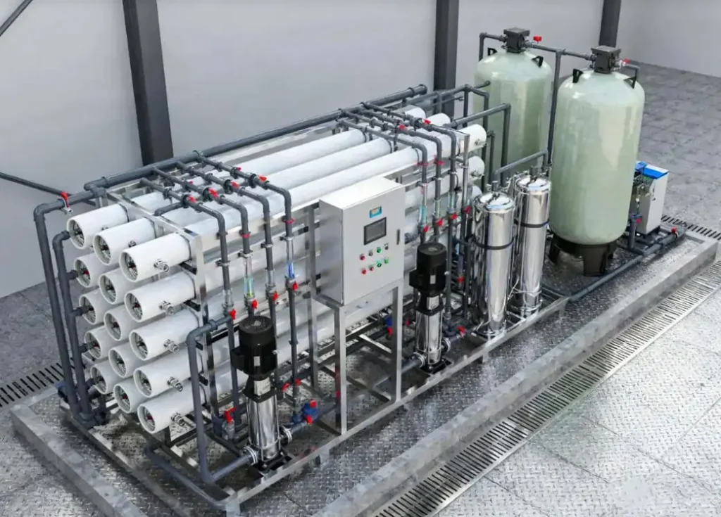
When selecting fiberglass RO pressure vessels for a reverse osmosis system, it is important to consider the following factors:
1. Pressure Requirements
- System Operating Pressure: Understanding the normal operating pressure of the RO system is critical when choosing a pressure vessel. Fiberglass RO pressure vessels are available in various pressure ratings, such as 150 PSI, 300 PSI, 450 PSI, 600 PSI, and 1000 PSI.
- For low-pressure systems, choosing a lower-rated vessel can meet requirements while reducing costs.
- For high-pressure systems, vessels must be able to withstand the system pressure to ensure safe and stable operation.
- Example: Small household RO systems typically operate at lower pressures, so 150 PSI or 300 PSI vessels may suffice, whereas large industrial RO systems may require 600 PSI or higher.
- Pressure Fluctuations: If the RO system experiences significant pressure fluctuations during operation, it is important to select vessels with a wider pressure tolerance and stronger strength. This prevents cracking or leakage under variable pressure conditions.
2. Size and Configuration
- Membrane Element Quantity and Size: Choose vessels according to the number and size of RO membrane elements used in the system. Vessels are available in various diameters and lengths, such as 4-inch and 8-inch vessels, and with 1 to 8 membrane elements per vessel.
- Example: If the system uses 8-inch membrane elements and requires 6 elements, an 8-inch 6-element vessel should be selected. This ensures sufficient space inside the vessel for proper water flow and filtration.
- Installation Space Constraints: Consider the available installation space. Compact vessels may be necessary for limited space. Connection types and interface dimensions should also be checked to ensure compatibility with other system components.
3. Water Quality Requirements
- Feed Water Characteristics: Analyze the raw water quality, including impurities, pH, salinity, and corrosive components. Poor-quality water with higher corrosive content requires vessels with strong corrosion resistance and anti-fouling properties. Fiberglass RO pressure vessels perform well in corrosion resistance, but for special water types, verify that the material and coating meet system needs.
- Permeate Water Quality: For systems requiring high-quality permeate water, sealing performance and filtration precision of the vessel are critical. Ensure that the vessel fits the RO membrane tightly to prevent untreated water from leaking into the permeate stream.
4. System Flow Requirements
- Design Flow Rate: The vessel’s internal diameter and length affect water flow speed and total flow. Select vessels that can handle the system’s designed flow rate.
- If the vessel’s capacity is too small, water production efficiency will decrease.
- If the vessel’s capacity is too large, it may cause excessive stress on the RO membranes, shortening their lifespan.
- Future Expansion: Consider potential system expansion. If more membranes or higher flow rates may be needed in the future, select vessels with sufficient extra capacity to allow for upgrades without replacing the entire system.
This guideline ensures that your selected fiberglass RO pressure vessels meet the RO system’s operational, spatial, water quality, and future expansion requirements, providing safe, efficient, and reliable long-term operation.
If you are not sure which RO pressure vessel suits your system, feel free to contact our team for professional advice.